
User Manual

6
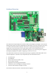
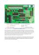
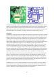
Figure 2: Functional blocks diagram: the key blocks are identified by coloured boundary marking. Please note that
the appearance of some components can vary.
This annotated photo of a populated (fully assembled) Gertboard shows where the functional blocks
are located. Some of the blocks have two areas marked. For example, the turquoise lines showing the
Atmel ATmega chip not only surround the chip itself and the header pins next to it (on the lower left)
but also surround two header pins near the bottom of the board, in the middle. These two pins are
connected to the Atmel chip and provide an easy way to interface the GPIO signals from the
Raspberry Pi (which are in the black box) with the Atmel chip.
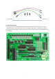
There is no connection (other than power and ground) between the different functional blocks on the
Gertboard. The many headers (the rows of pins sticking up from the board) allow you to make these
connections, using straps and jumpers. See Figure 11 on page 18 for an example of how these are
used to connect the various blocks together.