
User Manual


48
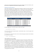
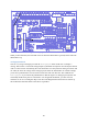
Figure 33: Wiring diagram for the sketch AnalogReadSerial.
GPIO14 and GPIO15 are the pins that the Raspberry Pi uses for the UART serial port. If you refer
back to the table of alternate functions (Table 1, page 11), you will see that GPIO14 is listed as TX
and GPIO15 as RX. This is not a mistake! This swapping is necessary: the data that is transmitted by
the ATmega is received by the Raspberry Pi, and vice versa.
Now, how to we get the Raspberry Pi to read and show us the data that the ATmega is sending out on
the serial port? There is a button labelled Serial Monitor on the toolbar of the Arduino IDE, but it
doesn‟t work on the Raspberry Pi. It assumes that you are talking to an Arduino board over USB, not
talking to a Gertboard over GPIO. The easiest way to retrieve this data is to use the minicom program.
You can install this easily by typing into a terminal this command:
sudo apt-get install minicom
You can use menus to configure minicom (by typing minicom –s). Alternatively, included with the
Gertboard software is a file minirc.ama0 with the settings you need to read from the GPIO UART
pins at 9600 baud. Copy this file (which was provided by Gordon Henderson) to /etc/minicom/
(you‟ll probably need to sudo this) and invoke minicom by typing
sudo minicom ama0
Now if you upload the sketch to the ATmega chip, you should see the value from the potentiometer
displayed in your minicom monitor.
LEDmeter Sketch
This example is one that we created specifically for the Gertboard, based on the AnalogInput
sketch described above. In the gertboard_sw directory, along with all the C files, is one called
LEDmeter.ino. This is an Arduino sketch that makes use of all 12 LEDs to create a bar graph