
User Manual


47
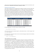
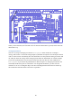
Figure 32: Wiring diagram for the AnalogInput sketch.
AnalogReadSerial Sketch Using Minicom
Some of the Arduino sketches involve reading or writing data via the serial port, or UART. An
example is AnalogReadSerial which is in File > Examples > Basics. This sketch sets the baud
rate to 9600, then repeatedly reads in a value from analogue pin 0 and prints this value to the serial
port (also called UART). The value read in is between 0 and 1023; 0 means that the input pin is at 0V
and 1023 means that it is at the supply voltage (3.3V for the Gertboard).
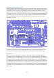
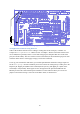
To set up your Gertboard for this sketch, you need the potentiometer attached to analogue input 0 as
for the AnalogInput sketch. In addition you need to connect the ATmega chip‟s UART pins to the
Raspberry Pi. Digital pin 0 (PD0 on the Gertboard) is RX (receive), and digital pin 1 (PD1 on the
Gertboard) is TX (transmit). These signals are also brought out to the pins labelled MCTX and
MCRX just above the GP15 and GP14 pins in header J2 on the Gertboard. Thus you can use two
jumpers to attach the ATmega‟s TX to GP15 and RX to GP14, as shown below.