
User Manual


46
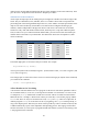
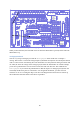
Figure 31: Wiring diagram for the sketch Button.
When you have done this, the first LED will be on when the third button is pressed, and off when the
third button is up.
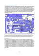
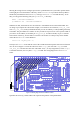
AnalogInput Sketch
Now let‟s try using an analogue pin. Find the AnalogInput sketch under File > Examples >
Analog. This reads in a value from analogue input 0 (which has already been converted by the internal
A/D to a value between 0 and 1023), then uses that number as a delay between turning an LED on and
off. Thus, the lower the voltage on the analogue pin, the faster the LED flashes. To run this example,
you‟ll need a potentiometer. The one used to test the A/D will work fine here. The comments for
AnalogInput say to connect the potentiometer so that the wiper is on analogue pin 0 (PC0 on the
Gertboard) and the outer pins are connected to +5V and ground. Remember, you must use 3.3V
instead of 5V as we‟re running the chip at 3.3V here. The diagram below shows how to connect up
the Gertboard to make this sketch work after it is uploaded.