
User Manual


45
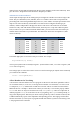
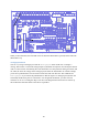
Figure 30: Circuit in use on the Gertboard, showing an additional 1k resistor to protect the input to BCM2835.
The 1K resistor between the pushbutton and the „Raspi‟ point is to protect the BCM2835 (the
processor on the Raspberry Pi) if you accidentally set the GPIO pin connected to „Raspi‟ to output
instead of input. The circuit to the right of the „Raspi‟ point happens on the Raspberry Pi: to use the
pushbutton we set a pull-up (shown as a resistor in the circuit above) on the pin so that the value read
is logical 1 when the button is not pressed (see page 19 for more info on the pull-up). The Gertboard
buttons are connected directly to ground so they cannot be made to read logic 1 when pressed. If you
want to use a Gertboard button with an Arduino sketch that assumes that the button reads 1 when
pressed, the best approach is to modify the sketch, if needed, so that it will invert the value it reads
from the button. For the pull-up, we can take advantage of the pull-ups in the ATmega chip. To do
this, find the lines below in the sketch
// initialize the pushbutton pin as an input:
pinMode(buttonPin, INPUT);
and insert the following two lines after them:
// set pullup on pushbutton pin
digitalWrite(buttonPin, HIGH);
To invert the value read from the button, find the line below:
buttonSate = digitalRead(buttonPin);
and insert a ! (the negation operator in C) as follows:
buttonSate = !digitalRead(buttonPin);
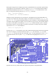
Now upload this modified sketch, as described for Blink. We still need to attach Arduino digial pin
2 (PD2 on the Gertboard, as you can see from the table) to a button, say button 3.The „Raspi‟ pin in
the circuit diagram above, which is where we want to read the value, is in the J3 header.