
User Manual


44
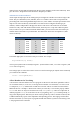
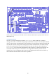
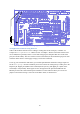
Figure 28: Wiring diagram for the sketch Blink.
Note that in this diagram we have not shown the connections to the SPI pins. Once you have uploaded
the code, you no longer need them and can remove the straps. On the other hand, if you want you can
leave them in place, and this is a good idea if you are planning on uploading some other sketches
later.
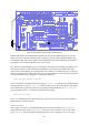
Button Sketch
Let‟s look at another fairly simple sketch called Button, located under File > Examples > Digital
menu in both 0018 and 1.0.1. The comments at the beginning of the sketch read
The circuit:
* LED attached from pin 13 to ground
* pushbutton attached to pin 2 from +5V
* 10K resistor attached to pin 2 from ground
Assuming that you have Blink working, your LED is already wired up, but what about the button?
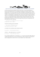
As mentioned above, since the ATmega chip on the Gertboard runs at 3.3V, we must replace the 5V
with 3.3V. So they suggest using a circuit like the one below, where the value read at pin 2 is logical 0
if the button is not pressed (due to the 10K pull-down resistor) and logical 1 if the button is pressed.
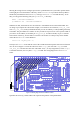
Figure 29: Suggested switch circuit for use with Button sketch.
However, the buttons on the Gertboard are used like this: