
User Manual


43
Uploading Sketches using the SPI Bus
In order to get your sketch running on the ATmega chip on the Gertboard, it has to be transferred over
to the chip somehow (this is called uploading the sketch). There are various methods used to program
ATmega chips, but we are going to use the SPI bus available on GPIO pins 8 through 11. This is
possible because your Arduino IDE is using the special downloader/uploader (avrdude) that you got
from projects.drogon.net. To set this up you need to connect the GPIO pins used for the SPI bus to the
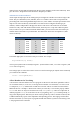
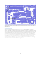
6-pin header J23, as in the diagram below. Here you are simply connecting the SPI pins in the GPIO
to the corresponding SPI pins in the header. The arrangement of the pins in J23 is shown in the
schematics, on page A-6.
Figure 27: The wiring diagram for uploading sketches to the ATmega microprocessor.
To upload your sketch to the chip in Arduino IDE choose File > Upload Using Programmer. It will
take a bit of time to compile and upload, and then your sketch is running on the microcontroller.
Blink Sketch
The Blink sketch is under the File > Examples > Basics menu. Bring it up and upload it to the
ATmega chip using the instructions above. The sketch is now running, but nothing is happening! On
most Arduino boards, pin 13 (the digital pin used by this sketch) has an LED attached to it, but not the
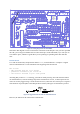
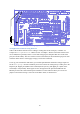
Gertboard. You have to wire up the LED yourself. Looking at Table 4 above, we see that digital pin
13 is labelled PB5 on the Gertboard, so you need to connect PB5 to one of the I/O ports. In the section
on Buffered I/O, LEDs, and Pushbuttons, we explained that you can make an LED show the value of
a signal by connecting that signal to one of the pins labelled BUF1 to BUF12 in the (unlabeled) single
row header at the top of the Gertboard. So if you connect PB5 to BUF1, as below, the first LED will
start to blink.