
User Manual


42
options for the ATmega168 and ATmega328, the ones most commonly used on the Gertboard). Then
go to the Tools > Programmer menu and choose “Raspberry Pi GPIO”.
Arduino Pins on the Gertboard
All the input and output pins of the ATmega chip are brought out to header J25 on the left edge of the
board. They are labelled PCn, PDn, and PBn, where n is a number. These labels correspond to the
pinout diagrams of the ATmega168/328 chips. However, in the Arduino world, the pin numbers of the
chips are not referred to directly. Instead there is an abstract notion of digital and analogue pin
numbers, which is independent of the physical devices. This allows code written for one Arduino
board to be easily used with another Arduino board, which may have a chip with a different pinout.
Thus, in order to use your Gertboard with the Arduino IDE, you need to know how the Arduino pin
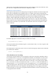
number relates to the labels on your Gertboard. The table below shows this correspondence (“GB”
means Gertboard).
Arduino Pin
GB pin
Arduino Pin
GB pin
Arduino Pin
GB pin
0
PD0
7
PD7
A0
PC0
1
PD1
8
PB0
A1
PC1
2
PD2
9
PB1
A2
PC2
3
PD3
10
PB2
A3
PC3
4
PD4
11
PB3
A4
PC4
5
PD5
12
PB4
A5
PC5
6
PD6
13
PB5
Table 4: The relationship between Arduino pin numbering and pins on the Gertboard.
In sketches digital pins are referred to with just a number. For example
digitalWrite(13, HIGH);
will set pin 13 (PB5 on the Gertboard) to logical 1. (In the Arduino world, LOW refers to logical 0, and
HIGH refers to logical 1.)
The analogue pins are referred to as A0 to A5. So to read from analogue pin 0 (PC0 on the Gertboard)
you would use the command
value = analogRead(A0);
A Few Sketches to Get You Going
A sketch is the name that Arduino uses for a program. It's the unit of code that is uploaded to and run
on an Arduino board (or, in our case, an ATmega microcontroller on a Gertboard). Let‟s have a look
at a simple one, Blink, which makes an LED turn on and off. This is accessible from the Arduino
IDE from the File > Examples > Basics menu. When you select this, a new window pops up with the
Blink code. There are only two functions in the code, setup and loop. These are required for all
Arduino programs: setup is executed once at the very beginning, and loop is called repeatedly, as
long as the chip has power. Note that you do not need to provide any code to call these functions; this
is added automatically as part of the compilation and uploading process. The language used in these
sketches is based on C, so the syntax in programs should look familiar if you have been looking at the
C test programs for the Gertboard.