
User Manual

41
selecting them for input and enabling a pull-up, as described on page 19) and to set GPIO11 to GP7,
GPIO4, GPIO1, and GPIO0 up as outputs (as described on page 13). Then we enter a loop where we
read the state of the pushbuttons and light up the LED corresponding to this number (after turning off
the LED previously set). We turn the LEDs on and off using GPIO_SET0 and GPIO_CLR0 as
described on page 21.
At the time of writing, there is no decoder test in Python.
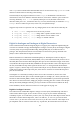
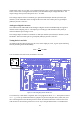
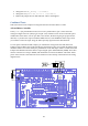
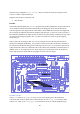
ATmega Device
The Gertboard can hold an Atmel AVR microcontroller, a 28-pin ATmega device, at location U8 on
the lower left of the board. This can be any of the following: ATmega48A/PA, 88A/PA, 168A/PA or
328/P in a 28-pin DIP package. Usually the 168 or 328 is fitted. The device has a 12MHz ceramic
resonator attached to pins 9 and 10. All input/output pins are brought out to header J25 on the left
edge of the board. There is a separate 6-pin header (J23 on the left side of the board) that can be used
to program the device.
The PD0/PD1 pins (ATmega UART TX and RX) are brought out to pins placed adjacent to the
Raspberry Pi UART pins so you only need to place two jumpers to connect the two devices.
Note that the ATmega device on the Gertboard operates at 3.3Volts. That is in contrast to the
„Arduino‟ system which runs at 5V. (This is the reason why the device does not have a 16MHz clock.
In fact at 3V3 the maximum operating frequency according to the specification is just under 12MHz.)
Warning: many of the Arduino example sketches (programs) mention +5V as part of the circuit.
Because we are running at 3.3V, you must use 3.3V instead of 5V wherever the latter is mentioned. If
you use 5V you risk damaging the chip.
The ATmega device and the headers connected to it are in the schematics on page A-6.
Programming the ATmega
Programming the ATmega microcontroller is straightforward once you have all the infrastructure set
up, but it requires a fair bit of software to be installed on your Raspberry Pi. We are very grateful to
Gordon Henderson, of Drogon Systems, for working out what needed to be done and providing the
customized software. Using his system, you can use the Arduino IDE (Integrated Development
Environment) on the Raspberry Pi to develop and upload code for the ATmega chip on the Gertboard.
All the software needed, along with instructions, is available at
https://projects.drogon.net/raspberry-pi/gertboard/
For the rest of this section, we assume that you have downloaded and successfully installed and
configured the Arduino IDE, as described at Gordon‟s website, and we proceed from there.
To get going with the ATmega chip, start up the Arduino IDE. This should be easy: if the installation
of the Arduino package was successful, you will have a new item “Arduino IDE” in your start menu,
under “Electronics”. The exact version of the IDE you get with depends on the operating system you
are using. The vast majority of Raspberry Pi users are using Raspbian, which is based on Debian
wheezy, so from now on we‟ll assume that you‟re running this. The version number is given in the
title bar; for wheezy it‟s 1.0.1. First you will need to configure the IDE to work with the Gertboard.
Go to the Tools > Board menu and choose the Gertboard option with the chip you are using (there are