
User Manual

40
The main loop is wrapped in a try: except: block to enable safe resetting of the ports in the
event of a CTRL+C keyboard interrupt.
Suggested safe tweaks to experiment with.
none this time
Decoder
The decoder implemented by the decoder program takes the three pushbuttons as input and turns on
one of 8 LEDs to indicate the number with the binary encoding given by the state of the buttons.
Switch S1 gives the most significant bit of the number, S2 the middle bit, and S3 the least significant
bit. For output, the LED D5 represents the number 0, D6 represents 1, and so on, so D12 represents 7.
Recall that the pushbuttons are high (1) when up and low (0) when pushed, so LED D12 is lit up when
no buttons are pressed (giving binary 111 or 7), D6 is lit up when S1 and S2 are pressed (giving
binary 001), etc.
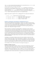
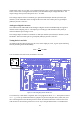
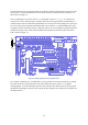
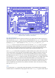
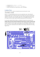
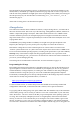
There is quite a bit of wiring for this one, as we are using all but one of the I/O ports.GPIO25 to
GPIO23 are reading the pushbuttons, so you need to connect GP25 to B1, GP24 to B2, and GP23 to
B3. The 8 lowest-numbered GPIO pins are used with I/O ports 5 to 12, so you need to connect GP11
to B5, GP10 to B6, GP9 to B7, GP8 to B8, GP7 to B9, GP4 to B10, GP1to B11, and GP0 to B12. In
addition, since we are using I/O ports 5 to 12 for output, you need to install all the out jumpers for
buffer chips U4 and U5 (recall that the out jumpers are those above the chips).
Figure 26: Wiring diagram for the decoder test.
Decoder Test in C
In the main routine for decoder, as always we start out by printing out to the terminal the
connections that need to be made on the Gertboard. Then we call setup_io to set up the GPIO
ready for use. Then we call setup_gpio to set GPIO25 to 23 for use with the pushbuttons (by