
User Manual

38
Change the 4 in adc_string = "{0:04d}"
Change the 3 in print "%s %s %s" % ("{0:03d}")
Remove the jumper between AD0 and DA1 and see what happens
Combined Tests
This section shows some examples of using more than one functional block at a time.
A/D and Motor Controller
In the potmot (for potentiometer-motor) test we use a potentiometer (“pot”) connected to the
analogue to digital converter (A/D) to get an input value, and this value is used to control the speed
and direction of the motor. It is set up so that at one extreme, the motor is going at top speed in one
direction, as you move the wiper towards the middle it slows, at the middle the motor stops, and as
you continue to move the wiper along, the motor speeds up again but in the other direction.
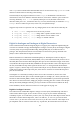
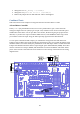
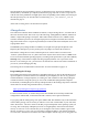
To wire up the Gertboard for this example, you combine the wiring for the A/D and motor tests.
Jumpers connect GP8 to GP11 to the pins directly above them to allow us to control the SPI bus using
GPIO8 to GPIO11. You must attach your potentiometer to the AD0 input. GPIO17 controls the motor
B input and GPIO18 controls the motor A input using the pulse width modulator (PWM). Thus GP17
must be connected via a strap to MOTB, and GP18 must be connected to MOTA. The motor and its
power source must be connected to the screw terminals in J19 at the top of the board. See the wiring
diagram below.
Figure 25: Wiring diagram for the potmot test.