
User Manual
37
potentiometer. It uses the display(char, reps, adc_value, spaces) function to
achieve this.
Moving the potentiometer while the program is running changes both the numerical readout and the
number of # characters displayed.
Suggested tweaks to experiment with. Try changing these one at a time and see what they do...
char = '#' – change value of char from # to a symbol of your choice (line 30)
sleep(0.05) – change the 0.05 and see what happens (line 56)
dtoa.py
The digital to analogue converter (D/A) is controlled by writing 2 binary bytes (16 bits in total) to it
via the SPI interface. The program uses a Python module called spidev to handle the SPI
communication. We have to give spidev two base 10 numbers, which it converts into 8-bit binary
bytes, which it sends to the D/A. The D/A outputs a voltage according to the value given to it. An
input of 0 gives 0V, 255 gives 2.048V, and it‟s linear in between, so 128 should give 1.02V.
The pre-determined values we send to the D/A are stored in two list variables...
num_list[] – holds the first byte (different for each channel).
common[] – holds the second byte of data (same for each channel).
The user chooses the channel and then the main loop takes the first number from each list and
combines byte1 with byte2. Then it sends them to the D/A, which immediately outputs the desired
voltage until enter is pressed. It iterates through all five values, setting the D/A and waiting for a key
press. Both channels are reset to zero at the end of the program.
Suggested tweaks to experiment with.
None this time. If you change the numbers in the lists you will break the program (the voltage
output will no longer agree with the numbers that the test program prints out). If you want to
see how they are derived, you can look in the dad.py program in the dac_write function
dad.py
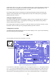
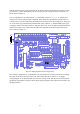
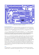
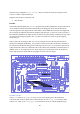
This program uses spidev to control the A/D and the D/A using both of the SPI ports on the Raspberry
Pi. First the wiring instructions are printed out on the screen. Then the main loops (one for each
direction) iterate from 0 to 256 and back again in increments of 32. This value is sent to the D/A using
dac_write(DAC_value), and the appropriate voltage appears on the ouput pin DA1.This
voltage goes by a jumper to AD0, an input of the A/D, and the get_adc(adc_channel) function
is called to read this voltage using the A/D, returning a number between 0 and 1023. Both numbers
are then printed out along with a bar chart (using the # character) representing the A/DC.
Suggested safe tweaks to experiment with.
Change the 32 in both loops for DAC_value in range(0,257,32) and for
DAC_value in range(224,-1,-32)