
User Manual
36
use, then calls setup_gpio to choose which pins to use and how to use them. In setup_gpio, as
usual INP_GPIO(n) (where n is the pin number) is used to activate the pins. This also sets them up
to be used as inputs. They should however, be used as an SPI bus, which is one of the alternative
functions for these pins (it is alternate 0). Thus we use SET_GPIO_ALT(n, a) (where n is the pin
number and a is the alternate number, in this case 0) to select this alternate use of the pins. Then the
program sends different values to the D/A and asks for real verification, using the multimeter, that the
D/A converter is generating the correct output voltage.
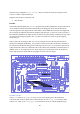
atod
To test the A/D, the atod program first asks which channel should be used and prints out the
connections required on Gertboard to run the program. Then it calls setup_io to get the GPIO
ready, then calls setup_gpio to choose which pins will be used, and how they will be used. The
setup_gpio used in atod works the same way as the one in dtoa (except for activating GPIO8
instead of GPIO7).
Then atod repeatedly reads the 10 bit value from the A/D converter and prints out the value on the
terminal, both as an absolute number and as a bar graph (the value read is divided by 16, and the
quotient is represented as a string of „#‟ characters). One thing to be aware of is that even if the
potentiometer is not moved, exactly the same result may not appear on successive reads. With 10 bits
of accuracy, it is very sensitive, and even the smallest changes, such as house current running in
nearby wires, can affect the value read.
dad
To test both the D/A and A/D at the same time, the dad test sends 17 different digital values to the
D/A (0 to 255 in even jumps, then back down to 0). The resulting values are then read in from the
A/D. Both the original digital values sent and the values read back are printed out, as is a bar graph
representing the value read back (divided by 16 as in atod). The bar graph printed out should be a
triangle shape: the lines will start out very short, then get longer and longer as larger digital values are
read back, then will get shorter again.
D/A and A/D tests in Python
The analogue to digital and digital to analogue converters are connected to the (SPI) ports on the
Raspberry Pi. These are the alternative functions of GPIO ports 7 and 8.
In order to make use of atod.py, dtoa.py and dad.py you must have SPI enabled, and you must
install a Python module called py-spidev. Instructions on how to do this are in the README.txt
included with the Python programs that you downloaded.
atod.py
The user chooses which channel to use on the analogue to digital converter (A/D), then wiring
instructions are printed out. The function get_adc(channel) uses spidev to read the A/D. It
receives three bytes of data and extracts the result – a number between 0 and 1023, where 0 means 0V
and 1023 means 3.3V.
The main loop runs 600 times with a “sleep” of 0.05s, so the program takes about 30 seconds (600 *
0.05) to run. During each iteration of the loop, the program reads the A/D and displays this reading
and a number of # symbols proportional to the value read, which depends on the position of the