
User Manual

34
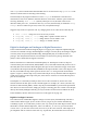
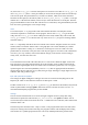
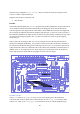
The red lead needs to be connected to DA0 (to test the D/A channel 0 which is shown below) or DA1
(for channel 1). Switch the multimeter on, and set it to measure voltages from 0 to around 5V. All
this is shown in Figure 22.
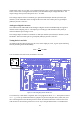
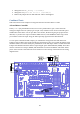
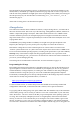
The C test program for the A/D is called atod; the Python version is atod.py. To run this test a
voltage source on the analogue input is required. This is most easily provided by a potentiometer (a
variable resistor). The two ends of the potentiometer are connected, one side to high (3.3V, which you
can access from any pin labelled 3V3) and the other to low (GND or ), and the middle (wiper) part
to AD0 (for channel 0 as shown below) or AD1 (for channel 1). To use the SPI bus jumpers should be
installed on the pins GP11, GP10, GP9, and GP8 connecting them to the SPI bus pins above them.
This is shown in Figure 23.
Figure 23: Wiring diagram for the test program atod.
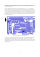
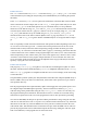
Even without a multi meter or a potentiometer, it is still possible to test the A/D and D/A by sending
the output of the D/A to the input of the A/D. The test that does this is called dad, for digital-
analogue-digital. To set the Gertboard up for this test, hook up all the SPI bus pins (connecting GP11
though GP7 with jumpers to the pins above them) and put a jumper between pins DA1 and AD0, as in
the diagram below.