
User Manual

33
assumes that writes are in 12 bits, so it is important that the value is selected appropriately (details are
below in the section “Testing the D/A and A/D”). The maximum output voltage of the D/A – the
output voltage when you send an input of all 1s – is 2.04V.
The analogue outputs of the two channels go to pins labelled DA0 (for channel 0) and DA1 (for
channel 1) in the J29 header on the left edge of the board. Just next to these pins are ground pins
(GND) to provide a reference.
Analogue to Digital Converter
The Gertboard uses a MCP3002 10-bit analogue to digital converter from Microchip. It supports 2
channels with a sampling rate of ~72k samples per second (sps). The maximum value (1023) is
returned when the input voltage is 3.3V.
The analogue inputs for these two channels are AD0 (for channel 0) and AD1 (for channel 1) in the
J28 header. Just next to these pins are ground pins (GND) to provide a reference.
Testing the D/A and A/D
According to the data sheet for the D/A, the value on the output pin, Vout, is given by the following
formula (assuming the 8-bit MCP4802):
Vout for channel 0 is DA0 in J29; for channel 1 it‟s DA1.
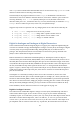
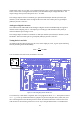
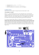
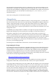
Figure 22: The wiring diagram for the dtoa test.
To test the D/A, a multi meter is required. The C test program for this is dtoa. The Python version is
dtoa.py. To set up Gertboard for this test, jumpers are placed on the pins GP11, GP10, GP9, and
GP7 connecting them to the SPI bus pins above them. Attach the multi meter as follows: the black
lead needs to be connected to ground. You can use any of the pins marked with or GND for this.