
User Manual

29
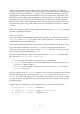
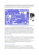
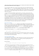
Figure 21: The wiring diagram for the test program motor.
Motor Test in C
The PWM is controlled by a memory map, like the GPIO and SPI bus. This memory map is part of
the setup_io function in gb_common.c, so that is whether the PWM is used or not. Further setup
code is found in, gb_pwm.c, with an associated header file gb_pwm.h. The function setup_pwm
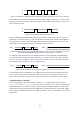
in gb_pwm.c sets the speed of the PWM clock, and sets the maximum value of the PWM to 1024:
this is the value at which the duty cycle of the PWM will be 100%. It also makes sure that the PWM is
off. The two routines set_pwm0 and force_pwm0 set the value that controls the duty cycle for the
PWM. set_pwm0 sets the value (first checking that it is between 0 and 1024), but as there are only
certain points in the PWM cycle where a new value is picked up, if a second value is written again
quickly the first will have no effect. The force_pwm0 routine takes two arguments, a new value and
a new mode. It disables the PWM, then sets the value, then re-enables it with the given mode setting,
with delays in strategic places to allow the new values to be picked up. The pwm_off routine simply
disables the PWM.
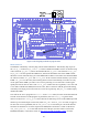
The code for the motor program is in motor.c. In the main routine, first the connections that must
be made on the board to run this program are printed out, then call setup_io to get the GPIO
interface ready for use. setup_gpio is then called to set GPIO18 up for use as the PWM output and
GPIO17 up for normal output. For the latter, both INP_GPIO and OUT_GPIO are used, see page 13
for more info. To set up GPIO18, first use INP_GPIO(18) to activate the pin. One of the alternate
functions for GPIO18 is to act as the output for the PWM; this is alternative 5. Thus use the macro
SET_GPIO_ALT(18, 5) to select this alternate use of the pin. (See table Table 6-31 from the
BCM2835 datasheet, or the online version at http://elinux.org/RPi_BCM2835_GPIOs, for more