
User Manual

28
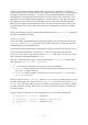
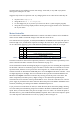
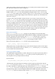
Figure 17: An example of a PWM output. Here the output is on for 50% of the time, so it has a duty cycle of 50%.
With a PWM, you can control the amount of time the output is high vs. when it is low. This is called
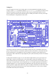
the duty cycle and is expressed as a percentage. Figure 17 above shows a 50% duty cycle; the one in
Figure 18 below is 25%.
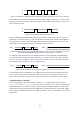
Figure 18: In this PWM example, the duty cycle is 25%.
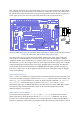
There is a PWM in the BCM2835 (the Raspberry Pi processor), and its output can be accessed via
GPIO18 (it is alternate function 5). If this is connected to one of the motor controller inputs (MOTA
has been used in our motor test), and the other motor controller input (MOTB in our test) is set to a
steady high or low, the speed and direction of the motor can be controlled.
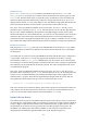
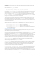
Figure 19: The motor direction is set by MOTB. Whilst MOTA has a duty cycle of 25%, the motor receives power
whenever MOTA and MOTB are different, thus it receives power for 75% of the time.
For example, in Figure 19 above we are alternating between A low/B high and A high/B high (the
second and fourth lines of the table above). When A is low, the motor will receive power making it
turn one way; when A is high it will not receive power. The end result for the 25% duty cycle shown
here is that the motor will turn one way at roughly ¾ speed.
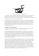
Figure 20: In this example, the motor will run in the opposite direction at around 25% speed.
If on the other hand you set MOTB low, as in Figure 20 above, then when A is high the motor will
receive power making it turn in the other direction, and when A is low the motor will not receive
power. The result for the 25% duty cycle is that it will turn in the other direction at about ¼ speed.
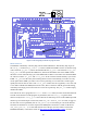
Testing the Motor Controller
The C test program for the motor controller is called motor. In Python there are two versions,
motor-rg.py and motor-wp.py. To set up Gertboard for this, connect GP17 in J2 to the MOTB
pin (the MOTB pin in J5, not the one at the top of the board), and GP18 to MOTA in J5. The motor
leads need to be connected to the MOTA and MOTB screw terminals at the top of the board, and the
power supply for the motor needs to be connected to the MOT+ and screw terminals. This is shown
in Figure 21.
0
1
0
1
0
1
0
1
MOTA MOTB
0
1
0
1
MOTA MOTB