
User Manual

27
ten times with a 0.4 second delay between each change. At the end, or on (CTRL-C) keyboard
interrupt, the GPIO ports are reset.
Suggested safe tweaks to experiment with. Try changing these one at a time and see what they do...
vary the 0.4 in sleep(0.4)
change the 10 in for i in range(10):
see what happens if you try to tell it you want to use driver 7 (when using the program)
change the error message displayed when choosing the wrong port number to an “alternative”
one of your choice
Motor Controller
The Gertboard has a ROHM BD6222HFP motor controller. The motor controller is for brushed DC
motors and can handle a maximum voltage of 18V and max current of 2A.
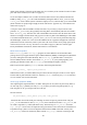
The controller has two input pins, A and B (labelled MOTA and MOTB on the board). The pins can
be driven high or low, and the motor responds according to the table below. The speed of the motor
can be controlled by applying a pulse-width-modulated (PWM) signal to either the A or B pin.
A
B
Motor action
0
0
no movement
0
1
rotate one way
1
0
rotate opposite way from above
1
1
no movement
Table 3: Truth table showing the behaviour of the motor controller under different logic combinations.
The motor controller IC has internal temperature protection. Current protection is provided by a fuse
on the Gertboard. The motor controller is in the schematics on page A-4.
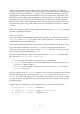
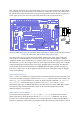
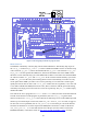
On the Gertboard functional block diagram (Figure 2 on page 6), the area containing the components
for the motor controller are outlined in purple. The motor controller and screw terminals are near the
top of the board, and there are two pins for the control signals in J5, a small header just above GP4
and GP1 in header J2. The MOTA and MOTB pins in J5 are the inputs to the motor controller – these
are digital signals (low and high). The screw terminals at the top of the board labelled MOTA and
MOTB are the outputs of the motor controller: they actually provide the power to the motor. The
motor will probably need more power (a higher voltage or current) than that provided by the
Gertboard. The screw terminals at the top labelled MOT+ and allow the connection of an external
power supply to provide this: the motor controller directs this power to the MOTA and MOTB screw
terminals, modulating it according to the MOTA and MOTB inputs in J5.
If you just want to turn the motor off and on, in either direction, this is achieved by simply choosing
two of the GPIO pins and installing straps between them to the MOTA and MOTB motor controller
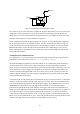
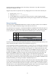
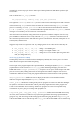
inputs. Then, to control the motor, the pins are set high or low as in Table 3. To control the speed of
the motor however, pulse width modulation (PWM) is required. This is a device that outputs a square
wave that flips back and forth from on to off very rapidly, as shown in Figure 17.