
User Manual

26
Now, when RLY1 in J4 is set low, the circuit doesn‟t receive any power and thus is off. When RLY1
in J4 goes high, the open collector driver uses transistors to connect the „ground‟ side of the circuit to
the ground on the board, and since this is connected to the ground terminal on the power supply, the
power supply powers your circuit: it is just turned off and on by the open collector driver.
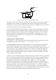
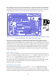
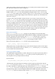
Figure 16: Wiring diagram to test the open collector drivers. On the right is a small test circuit made up of two LEDs
in series with a 90 Ω resistor, and a 9V battery acting as power supply.
You may wonder why you need to connect the positive terminal of the power supply to the open
collector driver (via the RPWR pin). The reason for this is that if the circuit happens to contain an
component that has electrical inductance, for example a motor or a relay, when the power is turned off
this inductance can cause the voltage on RLYn pin on the right of the board to quickly rise to a higher
voltage than the positive terminal of the power supply, dropping quickly afterwards. The chip itself
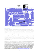
has an internal diode connecting the RLYn pin to RPWR (this is the diode at the top of Figure 15).
This allows current to flow to the top (positive side) of your circuit, allowing the energy to dissipate
and preventing damage.
Open Collector Test in C
The ocol test is very simple. First, it prints out the connections required on the board (and with your
external circuit and power supply), and then it calls setup_io to get the GPIO interface ready to use
and setup_gpio to set pin GPIO4 to be used as an output (using the commands INP_GPIO(4);
OUT_GPIO(4); as described on page 13). Then in it uses GPIO_SET0 and GPIO_CLR0
(described on page 21) to set GPIO4 high then low 10 times. Note: the test asks which driver should
be tested, but it only uses this information to print out the connections that need to be made.
Otherwise it ignores your response.
Open Collector Test in Python
The two open collector programs ocol-wp.py and ocol-rp.py are identical apart from the
GPIO system used. In the programs, the function which_channel() handles the user channel
selection. Once a suitable input is obtained, correct wiring instructions are displayed. Once enter is
pressed, to confirm the wiring is done, the program switches the chosen open collector port on and off