
User Manual

25
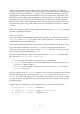
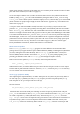
Raspi
OUT
common
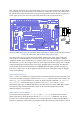
Figure 15: Circuit diagram of each open collector driver.
The „common‟ pin is, as the name states, common for all open collector drivers. It is not connected to
anything else on the Gertboard. As with all devices the control for the open collector drivers (the
„Raspi‟ point) can also be connected to the ATmega controller to, for example, drive relays or motors.
The open collector drivers are in the schematics on page A-3.
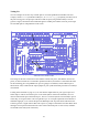
In the Gertboard functional block diagram (Figure 2 on page 6), the area containing the components
for the open collector drivers are outlined in yellow. The pins corresponding to „Raspi‟ in Figure 15
are RLY1 to RLY6 pins in the J4 header; the pins corresponding to „common‟ are the ones marked
RPWR in the headers on the right edge of the board; and the pins corresponding to „OUT‟ are the
RLY1 to RLY6 pins in the headers J12 to J17. How these are then used is demonstrated by the test
wiring and code examples.
Testing the Open Collector Drivers
The C program ocol (for open collector) allows the functional testing of the open collector drivers.
The Python version comes in two flavours, ocol-rg.py and ocol-wp.py.
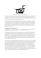
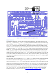
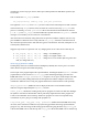
We needed something for the driver to switch on and off, so we created a little circuit consisting of
two large LEDs and a resistor in series. (This is the small circuit to the right of the Gertboard in
Figure 16.) Once connected, the forward voltage across each of these LEDs is a little above 3V, so we
used a 9V battery as a power supply and calculated a series resistance of around about 90Ω to set a
suitable current flow through the LEDs. You can of course use any circuit you like to test this; just
make sure that the voltage of your power supply is appropriate for your circuit (and that it is within
the 50V, 500mA limit of the driver).
To turn the circuit off and on using the open collector driver (say you want to use driver 1), first check
that your circuit works with the external power supply you are using. Then, leave the positive side of
your circuit attached to the positive terminal of the power supply, but in addition connect it to one of
the RPWR pins in the headers on the right edge of the board (they are all connected together).
Disconnect the ground side of the circuit from the power supply and connect it instead to RLY1 in
header J12 on the right of the board. Attach the ground terminal of the power supply to any GND or
pin on the board. Now, we need a signal to control the driver. For the ocol test we use GPIO4 to
control the open collector (you could of course use any logic signal), so connect GP4 in header J2 to
RLY1 in J4. (To test a different driver, say n, connect the ground side of the circuit up to RLYn in the
headers on the right of the board and connect GP4 in header J2 to RLYn in J4.)