
User Manual
24
Butled Test in C
In butled.c we use INP_GPIO to set GPIO22 and GPIO23 to input and GPIO_PULL and
GPIO_PULLCLK0 to set the pull-up on GPIO23. This is described in more detail on page 19, in the
buttons test. Then the GPIO values are repeatedly read in, and the binary values of GPIO22 and
GPIO23 are printed out (with GPIO23 first), if they have changed since the last cycle. So if „01‟ is
displayed on the monitor, we can see that GPIO23 is low and GPIO22 is high. (Note that the LED for
port 6, labelled D6, should be off when switch 3 is pressed and on when switch 3 is up.)
Now, if the values for GPIO22 and GPIO23 are always the same, „00‟ and „11‟ will only ever be
printed out. But occasionally we see „01‟ or „10‟. Note that when this occurs, the first digit changes to
the new value, and then immediately afterwards the second digit changes. But the values of both
GPIO22 and GPIO23 are read out simultaneously, so why do we ever have different values on the two
GPIO pins? The answer is that signal from the pushbutton (which is connected to GPIO23) takes a
small amount of time to propagate through the buffers to get to GPIO22. Sometimes we take a reading
after GPIO23 has changed, but insufficient time has passed for GPIO22 to change state and follow it!
Butled Test in Python
This program (butled-rg.py) also only works with RPi.GPIO at the moment. It is a very similar
program to buttons, but with two less buttons in use and an LED wired into the circuit, which lights
on button press.
Two GPIO ports are used. One (23) is pulled HIGH for the button and the other (22) is configured as
a regular input. In the main while loop, the program polls both ports and, if there is a change,
increments the variable button_press and displays the new values on the screen. The strap from
U3-out-B3 pin 1 to BUF6 in the top header connects the LED to the button, causing it to light and the
other input port (22) to go HIGH when the button is pressed. The values are displayed on the screen
as with the buttons program.
Now, if the values for GPIO22 and GPIO23 are always the same, „00‟ and „11‟ will only ever be
printed out. But occasionally we see „01‟ or „10‟. Note that when this occurs, the second digit changes
to the new value, and then immediately afterwards the first digit changes. This is opposite of the
behaviour of the C program, where the first digit sometimes changes before the second. Why is it
acting differently? In the Python code, the values are read in by this line of code:
status_list = [str(GPIO.input(23)),str(GPIO.input(22))]
This causes GPIO23 to be read before GPIO22. If the button is pressed or released between these two
reads, GPIO23 will still have the old value, but the new value will be read from GPIO22. The new
value won‟t be read from GPIO23 until the next time through the while loop.
Open Collector Driver
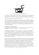
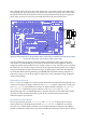
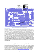
The Gertboard uses six ports of a ULN2803a to provide open collector drivers. These are used to turn
off and on devices, especially those that are powered by an external power supply and need a different
voltage or higher current than that available on the Gertboard. Basically, an open collector connects
the ground side of an external circuit to ground on the board, thus giving the circuit power. The
ULN2803A can withstand up to 50V and drive 500mA on each of its ports. Each driver has an
integrated protection diode (the uppermost diode in the circuit diagram in Figure 15).