
User Manual

23
Testing I/O
Our two examples so far have only used the ports to access the pushbuttons and LEDs. The next
example, called butled (for BUTton LED) in C, or butled-rg.py (in Python), will show one of
the ports serving just as an input port. The idea is that one port (along with its button) is used to
generate a signal, and software then sends that signal to another port which it is used as just an input.
We read both ports in and print them on the screen.
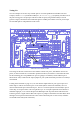
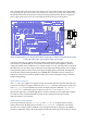
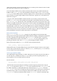
Figure 14: The wiring diagram for test program butled which detects a button press, and then displays that button
state on the screen and on an LED.
The wiring for this test is shown above. Pin GPIO23 controls I/O port 3, and GPIO22 controls I/O
port 6, so GP23 in header J2 is connected to pin B3 in header J3, and GP22 is connected to B6. Now
for the interesting part. The pushbutton on port 3 is going to be used here, but the LED for port 3
should not be used, so therefore the output jumper for port 3 (which would be placed at U3-out-B3) is
not installed.
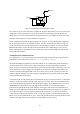
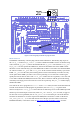
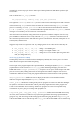
Looking at the schematic on page A-2, it is clear that the output buffer for port 3 goes to pin 14 of
buffer chip U3. This is connected to pin 1 of U3-out-B3 (shown as P6 in the schematic). It is not
obvious which header pin on the board is pin 1, but as it‟s connected (on the circuit board) to pin 14
of the chip, we can guess that it‟s the one right above pin 14. A simple experiment shows that this is
indeed the right pin, so we connect this pin to the BUF6 pin at the top of the board. This allows the
switch to generate a signal which is then sent to port 6. A jumper is installed across U4-in-B6 to allow
that signal to be input from the board. The value of the switch from port 3 is also read in, and these
two should be the same (most of the time).