
User Manual

21
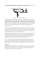
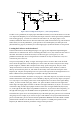
If there aren‟t enough jumpers or straps to wire these connections all up at once, don‟t worry. Just
wire up as many as possible and run the test. Once it‟s finished the straps/jumpers can be moved and
the test can be run again. Nothing bad will happen if you write to an unconnected pin.
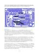
Figure 13: The wiring diagram for the LED test program
LEDs Test in C
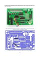
The test code in leds.c first calls setup_io to get everything ready. Then setup_gpio is
called, which prepares 12 GPIO pins to be used as outputs (as all 12 I/O ports will require
controlling). All of the GPIO signals except GPIO 0, 1, 4, 14, and 15 are used. To set them up for
output, first call INP_GPIO(n) (where n is the GPIO pin number) for each of the 12 pins to activate
them. This also sets them up for input, so then call OUT_GPIO(n) afterwards for each of the 12 pins
to put them in output mode.
LEDs are switched on using the macro GPIO_SET0: the value assigned to GPIO_SET0 will set
GPIO pin n to high if bit n is set in that value. When a GPIO pin is set high, the I/O port connected to
that pin goes high, and the LED for that port turns on. Thus, the line of code “GPIO_SET0 =
0x180;” will set GPIO pins 7 and 8 high (since bits 7 and 8 are set in the hexadecimal number
0x180). Given the wiring setup above, ports 11 and 12 will go high (because these are the ports
connected to GP7 and GP8), and thus the rightmost two LEDs will turn on.
To turn LEDs off, use macro GPIO_CLR0. This works in a similar way to GPIO_SET0, but here the
bits that are high in the value assigned to GPIO_CLR0 specify which GPIO ports will be set low (and
hence which ports will be set low, and which LEDs will turn off). So for example, given the wiring
above, the command “GPIO_CLR0 = 0x100;” will set GPIO8 pin low, and thus turn off the LED
for port 11, which is the port connected to GP8. (In leds.c the LEDs are always all turned off
together, but they don‟t have to be used this way.)