
User Manual
20
Note that because of the way Python for loops work, the end point of the loop must be set to one
beyond the last item in the range that you want to cover. So in order to set port 25, the end point of the
loop command must be set to 26.
Next, the wiring instructions appear on the screen. Once the user confirms that the wiring is ok, the
initial values for variables button_press and previous_status are set.
Next a while loop runs until 19 button presses/releases have occurred. For each iteration of this
loop, the status of each button is read and, if pressed, a 1 is stored in a list variable called
status_list. If not pressed, a 0 is stored.
Then the status_list values are all checked against the previous_status. If there‟s a
change, this line
if current_status != previous_status:
executes a small section of the program that displays the new values on the screen, increments the
value of the iterator button_press, and the loop starts again from the top. Now it‟s one button
press closer to the end-point of 19.
The while loop is enclosed in a try block:
try:
<while block>
except KeyboardInterrupt:
This enables the program to reset the ports if CTRL+C is pressed to terminate the program early.
If the program ends normally, after 19 button presses, the ports will be reset anyway. If we hadn‟t
included the try: except: block, a keyboard interrupt (ctrl-c) would close the program but leave
the ports open. This would give errors if you tried to use the ports again.
Suggested tweaks to experiment with. Try changing these one at a time and see what they do...
while button_press < 20: – change the 20 to some other number
button_press += 1 – change the 1 to some other number
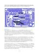
Testing the LEDs
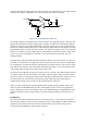
The C test program for the LEDs is called leds. The Python versions are leds-rg.py and
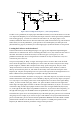
leds-wp.py. To set up the Gertboard to run this test, see the wiring diagram in Figure 13. Every
I/O port is connected up as an output, so all the „out‟ jumpers (those above the buffer chips) are
installed. Straps are used to connect the following (where all the „GP‟ pins are in header J2 and all the
„B‟ pins are in header J3): GP25 to B1, GP24 to B2, GP23 to B3, GP22 to B4, GP21 to B5, GP18 to
B6, GP17 to B7, GP11 to B8, GP10 to B9, GP9 to B10, GP8 to B11, and GP7 to B12. In other words,
the leftmost 12 „GP‟ pins are connected to the „B‟ pins, except that GP14 and GP15 are missed out:
they are already set to UART mode by Linux, so it‟s best if they are not touched.