
User Manual

18
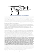
GPIO23 will read the rightmost pushbutton. The jumpers on the „out‟ area of U3 (U3-out-B1, U3-out-
B2, U3-out-B3) are optional: if they are installed, the leftmost 3 LEDs will light up to indicate the
state of the switches.
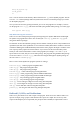
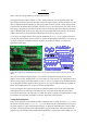
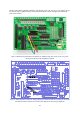
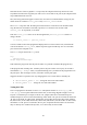
Figure 11: Photo showing connections for the buttons test. Whilst the image above is clear, it isn’t very good at
showing exactly how the straps and jumpers are placed.
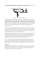
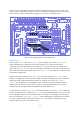
Figure 12: Wiring diagram for buttons test. This type of diagram is much more effective at showing the connections
that need to be made, so from now on, we will use these diagrams to show wiring arrangements.