
User Manual

17
This is not an I/O voltage which can be reliably seen as low.
The output and input jumper locations are above and below the U3, U4, and U5 buffer chips. The
input jumpers need to be placed on the headers below the chips (shown on the board with the „in‟ text;
they are separated from the chip they go with by four small resistors), and the „output‟ jumpers need
to be placed on the headers above the chips (with the „out‟ text). If viewed closely (it is clearer on the
blue and grey diagram), it is possible to see that each row of 8 header pins above and below the buffer
chips is divided up into 4 pairs of pins. The pairs on U3 are labelled B1 to B4, the ones on U4 are B5
to B8, and the ones on U5 are B9 to B12. The B1 pins are for port 1, B2 for port 2, etc.
To use port n as an input (but not when using the pushbutton, if n is 1, 2, or 3), a jumper is installed
over the pair of pins in Bn in the row marked „in‟ (below the appropriate buffer chip). To use port n as
an output, a jumper is installed over the pair of pins in Bn in the row marked „out‟ (above the
appropriate buffer chip).
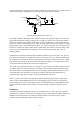
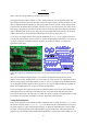
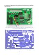
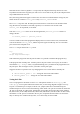
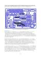
Figure 10: Example of port configuration where ports 1 to 3 are set to be outputs and ports 10 and 11 are set to be
inputs.
As a concrete example, in Figure 10 ports 1, 2, and 3 are configured for output (because of the
jumpers across B1, B2, and B3 on the „out‟ side of chip U3). Ports 10 and 11 are configured for input
(because of the jumpers across B10 and B11 on the „in‟ side of U5). Figure 10 also demonstrates why
we use diagrams instead of photos to show you how to wire up your Gertboard. The input jumper on
B10 is almost impossible to see because it is shorter than the others.
In the test programs, the required connections are printed out before the tests are started. The input
and output jumpers are referred to in the following way: U3-out-B1 means that there is a jumper
across the B1 pins on the „out‟ side of the U3 buffer chip. So the 5 jumpers in the picture above would
be referred to as U3-out-B1, U3-out-B2, U3-out-B3, U5-in-B10, and U5-in-B11.
Testing the Pushbuttons
There are test programs for the buttons in both C and Python. The C version is called buttons, and
the Python version is called buttons-rg.py. To run these tests, the Gertboard must be set up as in
the photo in Figure 11. (The wiring diagram in Figure 12 shows the same thing more clearly.) There
are straps connecting pins B1, B2, and B3 in header J3 to pins GP25, GP24, and GP23 in header J2
(respectively). Thus GPIO25 will read the leftmost pushbutton, GPIO24 will read the middle one, and