
User Manual

15
output from the RPi. It is important to keep this in mind as the Gertboard is set up: an output from the
Gertboard is an input to the Raspberry Pi, and so the input jumper must be installed.
I/O
1k
1k
74xx244input output
Raspi
10k
3.3V
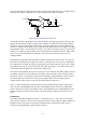
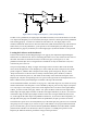
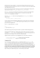
Figure 8: The circuit diagram for I/O ports 4-12.
The triangle symbols in the diagram above represent buffers; they propagate logical values (low and
high) in the direction the triangle is pointing. The rectangles are resistors, the black triangle and line
with arrows coming out is an LED, and the hollow circles are header pins. In order to make the port
function as an input to the Raspberry Pi you install the input jumper (shown in the diagram as a staple
shape labelled „input‟): then the data flows from the „I/O‟ point to the „Raspi‟ point. To make the port
function as an output, the output jumper must be installed: then the data flows from the „Raspi‟ point
to the „I/O‟ point. If both jumpers are installed, it won‟t harm the board, but the port won‟t do
anything sensible.
In both the input and output mode the LED will indicate what the logic level is on the „I/O‟ pin. The
LED will be on when the level is high and it will be off when the level is low. There is a third option
for using this port: if neither the input nor output jumper is placed the I/O pin can be used as a simple
logic detector. The I/O pin can be connected to some other logic point (i.e. one that is either at 0V or
3.3V) and the LED will show if the connect point is high or low.
The resistor on the right side of Figure 8 is a pull-up. If it were not there, the LED would turn off and
on with the smallest of electronic changes, for example, when the board is simply touched. Turning
the LED on when it is not being driven prevents this seemingly random behaviour and also serves as
an indicator that your Gertboard is receiving power properly. Note that if the output jumper is
installed but the „Raspi‟ point is not driven, the random behaviour will return.
There is a series resistor between the input buffer (the left-pointing triangle) and the „Raspi‟ point.
This is to protect the BCM2835 (the processor on the Raspberry Pi) in case the user programs the
GPIO as output but leaves the input jumper in place. The BCM2835 input is a high impedance input
and thus a 1K series resistor will not produce a noticeable change in behaviour when it is used as
input.
Pushbuttons
The Gertboard has three pushbuttons; these are connected to ports 1, 2, and 3. The circuit for these
ports is shown in Figure 9. This circuit is essentially the same as that in Figure 8 with the addition of a
pushbutton switch and resistor on the left side. When the button is pressed, the „Raspi‟ point is
connected to ground (through a resistor) and so reads low.