
Data Sheet
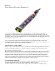
standard off-the-shelf components. In addition to the supplied set of mixed signal clips it means the full
range of scope probes designed for any BitScope can be used. In fact probes sourced from anywhere
can be used so if you already have them, they’ll work with BS05. For example, use 10:1 probes when a
higher input impedance is required or when looking at voltages higher than 12V. BS05 is not designed
for use with the dual channel active differential probe.
It’s an eight channel logic analyzer
BS05 also have an 8 channel logic analyzer built-in. BS05 is very similar to BS10 in terms of its digital
inputs and logic analysis features. The six channels L0 to L5 are CMOS 3.3/5V compatible and
switching levels are suitable for both logic families. These inputs all have 100k/5pF input impedance.
For example, doubling the input range is as simple as inserting a 100k resistor in series. Logic channels
L6 and L7 are special; their inputs are derived from the analog channels CHA and CHB via the user
adjustable analog trigger comparators. In addition to being able to capture and display the trigger
signals from the analog channels it means the analog channels may be used as logic inputs with
variable switching levels. For example, these two channels can be used to capture 1.2V or 1.8V logic
families or 12V, 24V or other PLC logic levels.
It’s an abitrary waveform and clock generator
BS05 would not be complete without the ability to generate waveforms and drive clocks. The standard
waveform control panel can generate sinunsoidal, triangle, sawtooth and square waveforms out of the
box. The waveform generator in BS05 itself is completely arbitrary; it can replay any wavetable of up
to 1024 sample points programmed into it. It could not be easier to get started. Simply connect the
supplied loop back wire from the L4/AWG pin or the L5/CLK pin to any input channel to experiment
with waveforms and clocks. You can use the waveform or clock generators to calibrate oscilloscope
probes, drive digital logic or test analog circuits such as amplifiers and signal processing systems.
The waveform and clock generators operate concurrently with the oscilloscope and logic analyzer
functions. This means you can use it to drive logic circuits while monitoring the results or use impulse
or step functions to evaluate analog system responses. You can vary the waveform parameters in real-
time to produce dynamically changing waveforms.
It’s a Spectrum Analyzer too
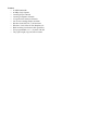
There’s a lot you can see in the time domain but for complete systems analysis you’ll need a spectrum
analyzer too. BS05 can be used as a powerful real-time mixed domain (time and frequency) spectrum
analyzer. It can be used in baseband or narrow band (RF) applications. The example above shows white
noise passed through a 20 kHz audio amplifier where the roll off starts at 15 kHz to -3dB at 17 kHz,
-20dB at 20kHz and -50dB beyond 22kHz. The spectrum analyzer is mixed domain; it operates in real-
time simultaneously as the waveform is displayed. It can provide some very good insights into the
operation of analog, RF & communications.
All in real-time
BS05 is all these test, measurement & data acquisitions systems in one tiny low cost device. Most
functions can operate concurrently and the BS05 is very fast with a frame rate up to 50 Hz driving a
digital phosphor display. It may be small and very low cost but works just like a quality stand-alone
mixed signal oscilloscope. View waveforms, plots, spectra and more on its smooth flowing real-time
display. Even live captured logic data can be viewed this way. With its large buffers it can support very
high speed one-shot capture for such a small device with post-capture zoom, scrolling and
measurement. Alternatively stream capture direct to disk for off-line replay and analysis.