
Datasheet

14 | Page
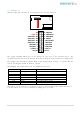
5.3 Atmega-48
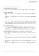
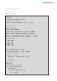
All unused pin of the Atmega-48 are brought out to a 20 -pin connector:
1
1
11
1
1
1
1
1
1
20
13 : PB5/SCK
12 : PB4/MISO
11 : PB3/MOSI
10 : PB2/SS
9 : PB1/PCINT1
8 : PB0/CLK0
7 : PD7/AIN1
6 : PD6/AIN0
5 : PD5/T1
GroundGround
T0/PD4 : 4
TXD/PD1 : 1
RXD/PD0 : 0
ADC3/PC3 : A3
ADC2/PC2 : A2
ADC1/PC1 : A1
ADC0/PC0 : A0
VBAT/5V
5V
The supply 5V/VBAT which goes to the Atmega-48 also goes to the connector pin 3. Any
equipment connected to that pin will also draw current from the battery if the 5V is switched off.
The supply comes through a Schottky diode so the actual voltage is lower: ~4.5 Volts. Also the
current consumption should be limited ~100mA.
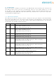
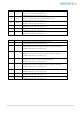
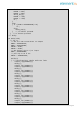
The following pins of the ATmega-48 are dedicated connected:
Pin
Hard wired to
Function
PD2
5V Supply
Detect absence of 5V supply (for RTC)
PD3
IRDA output
Receive IRDA signal
PC5
SCL
I
2
C connection with the Pi
PC4
SDA
I
2
C connection with the Pi
PB7
XTAL1
32768Hz Tuning crystal
PB6
XTAL2
32768Hz Tuning crystal
PC6
Program reset
Reset when programming
The Atmege-48 does not have a dedicated reset pin as that would interfere with its function as
real-time-clock. A reset can be obtained by pulling pin 4 of J13 low.