
Datasheet

13 | Page
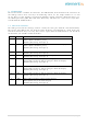
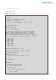
5.2 Atmega-328
The Atmega-328 pins are brought to connectors compatible with the Arduino-Uno.
J14 J7
1 1
11
1
1
1
1
1
1 1
11
1
1
1
1
1
Pin
No.
Signal
Pin
No.
Signal
10
A5/PC5/SCL
8
7/PD7/AIN1
9
A4/PC4/SDA
7
6/PD6/AIN0/LED6
8
AREF
6
5/PD5/T1/LED5
7
Ground
5
4/PD4/T0
6
13/PB5/SCK/LED0
4
3/PD3/INT1/LED4
5
12/PB4/MISO
3
2/PD2/INT0
4
11/PB3/MOSI
2
1/PD1/TXD
3
10/PB2/SS/LED2
1
0/PD0/RXD
2
9/PB1/PCINT1/LED1
1
8/PB0/CLK0
Pin 1 is on the right-hand side so these tables top-to-bottom are the pins from left-to-right.
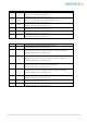
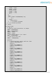
J9 J6
1 1
11
1
1
1
1
1
1 1
11
1
1
1
1
1
Pin
No.
Signal
Pin
No.
Signal
8
NC
6
A5/PC5/SCL
7
Ground
5
A4/PC4/SDA
6
Ground
4
A3/PC3/ADC3/BUT1
5
5V
3
A2/PC2/ADC2/BUT0
4
3V3
2
A1/PC1/ADC1
3
Reset (Active low)
1
A0/PC0/ADC0
2
5V
1
NC
Pin 1 is on the left-hand side so these tables top-to-bottom are the pins from right-to-left.
Beware that Pin 8 of J9 is normally connected directly to the input voltage which has been
removed and thus is NC here.