GertDuino Board Exclusively From User Manual By: G.J. van Loo, Version 1.
1 Contents Contents .......................................................................................................................... 2 1 Introduction ........................................................................................................................................ 3 2 3 4 5 1.1 Identify......................................................................................................................................... 3 1.2 Comparison ...........................
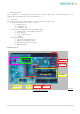
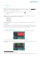
1 Introduction The GertDuino is a Raspberry-Pi add-on board which offers the same functionality as an Arduino-Uno but with some extra added features. 1.1 Identify The picture below lets you identify the various functions on the board. • RS232 level converter can be used by: o Raspberry-Pi o or Atmega-328 o or Atmega-48 • Atmega 328 (Arduino-Uno® compatible) with: o Arduino-Uno® compatible connectors o Reset button o 2 user push buttons o 6 LEDs. • Atmega 48 with: o I/O connector with 20 pins.
1.2 Comparison There are some differences between a normal Arduino-Uno and the GertDuino. Function USB Reset button Power supply 3V3 supply LED's User pushbuttons RS232 buffer Real-Time-Clock Infra-red interface Arduino-Uno Slave interface Yes 7..12V, ~250mA ~50mA One Not-buffered - GertDuino Yes <5V Raspberry-Pi> ~150mA. Six Buffered Two Yes Yes Yes Table 1: Comparison GertDuino vs Arduino-Uno 1.3 Vext As the board does not have a separate supply the Vext is not connected.
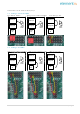
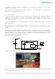
Connections can be made in many ways: 2.1 Atmega-328 & Pi UART Pi to RS232 buffers Atmega-328 to RS232 buffers Raspberry-Pi Atmega 328 Atmega 328 Atmega 328 RS232 buffers RS232 buffers Atmega 48 Atmega 48 Atmega 48 2.
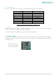
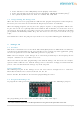
3 3.1 Atmega-328 Features This device is compatible with the Arduino Uno. In contrast to the 328 on the GERTBOARD this device runs of 5V, has the 16MHz oscillator and has connectors which are 100% Arduino-Uno compatible. It also contains the reset switch. This board also has the following components which you will not find on the Uno: • 2 User push buttons • 6 LEDs 1 LEDs One LED is connected to PB5 (aka Port-13 aka SCK). This is compatible with the UNO. The GertDuino has a five more LEDs.
At the left there are the GND (white) and 5V (Purple) connections. At the top row right are the Reset (green), Mosi (Red), Clk (Black) and Miso (Grey)2. The equivalent JTAG names for these are: nSRST, TDI, TCK, TDO 3.3 Using/running the Atmega-328 When the device has been programmed it will run that program independent of the RaspberryPi. In fact you can remove the board from the Raspberry-Pi and use it standalone.
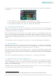
To program the 48 using a JTAG-ICE you need to use the "squid" cable and make the following connections: At the left there are the GND (white) and 5V (Purple) connections. At the bottom row right are the Reset (green), Mosi (Red), Clk (Black) and Miso (Grey).3 The equivalent JTAG names for these are: nSRST, TDI, TCK, TDO 4.
The IRDA can also be used if the GertDuino is used stand-alone to control the connected logic using a remote control. Note that 95% of all TV/Video/CD remote controls use the 38KHz infra-red signal, but the coding varies greatly from type to type. 4.6 Battery Drain If a battery is present and the power of the Raspberry-Pi is switched of the Atmega-48 will still remain powered by the Battery. It will also keep running.
If possible limit the current from your power source to a few milli-amps. I managed to blow a fuse of my meter performing the measurements because I accidentally shorted the supply when placing the probe on the battery holder. 4.7 Atmega-48 LED trick If you are debugging, an LEDs is often the first tool you reach for. But the Atmega-48 does not have any LEDs. However the Atmega-328 does! There are two ways in which you can use these LEDs : • • The safest way is to remove the 328 from its socket.
5 Connectors The board contains a number of connectors. You will find that in the document the connectors of the Atmega devices have two ways of numbering: There are the single numbers 0..13 and A1..A3. These are the numbers used in many Arduino example programs. Alongside those I use the official pin names (PB0..PB7, PD0..PD7, PCO..PC3). The latter are easier to use if you have to work with the AVR datasheet. 5.1 Alternate functions.
# Name Functions ADC5 (ADC Input Channel 5) SCL (2-wire Serial Bus Clock Line) PCINT13 (Pin Change Interrupt 13) ADC4 (ADC Input Channel 4) SDA (2-wire Serial Bus Data Input/Output Line) PCINT12 (Pin Change Interrupt 12) ADC3 (ADC Input Channel 3) PCINT11 (Pin Change Interrupt 11) ADC2 (ADC Input Channel 2) PCINT10 (Pin Change Interrupt 10) ADC1 (ADC Input Channel 1) PCINT9 (Pin Change Interrupt 9) ADC0 (ADC Input Channel 0) PCINT8 (Pin Change Interrupt 8) A5 PC5 A4 PC4 A3 PC3 A2 PC2 A1 PC1 A0
5.2 Atmega-328 The Atmega-328 pins are brought to connectors compatible with the Arduino-Uno. J14 J7 1 1 1 1 1 1 1 1 1 1 1 1 1 1 Pin No. 10 9 8 7 6 5 4 3 2 1 1 1 1 Signal Pin No.
5.3 Atmega-48 All unused pin of the Atmega-48 are brought out to a 20 -pin connector: 1 1 1 1 1 1 1 1 5V VBAT/5V ADC0/PC0 : A0 ADC1/PC1 : A1 ADC2/PC2 : A2 ADC3/PC3 : A3 RXD/PD0 : 0 TXD/PD1 : 1 T0/PD4 : 4 Ground 1 20 1 13 : PB5/SCK 12 : PB4/MISO 11 : PB3/MOSI 10 : PB2/SS 9 : PB1/PCINT1 8 : PB0/CLK0 7 : PD7/AIN1 6 : PD6/AIN0 5 : PD5/T1 Ground The supply 5V/VBAT which goes to the Atmega-48 also goes to the connector pin 3.
5.4 Raspberry-Pi All connections between the board and the Raspberry-Pi are protected against 5V signals. The I2C bus has FET level switches. All the other signals use resistive dividers.
6 Frequently Asked Questions (FAQs) Some questions you may ask and the answers. avrdude: AVR device not responding Q: When I try to program the device I get an error: "avrdude: AVR device not responding." A: The most likely cause is that you have forgotten to place the four programming jumpers. See section 3.2 Program the Atmega-328. Why is my program slow? Q: When I run the program it is very slow. Where I expect a delay of 1second it takes much longer.
7 How to start Before you can program the devices you need to have a cross compiler. A cross compiler is a compiler which runs on one type of processor, but generates code for a different type. In this case the compiler runs on the Raspberry-Pi (ARM11 device) but makes code for the Atmel devices. 7.
Alternative is that you buy a JTAG-ICE box and use that to program and the devices but that is a lot more expensive. It does have the advantage that you can use it for debugging as well: Step through the program, set breakpoints ,inspect variables etc.
8 8.1 Example programs Atmega-328 blink.c source code: /* * blink.c * * Created: 23/09/2013 21:04:02 * Author: G.J. van Loo * Simple example program to 'walk' the LEDs */ #include
oldd = PORTD; PORTB = 0xFF; PORTD = 0xFF; delay_ms(1); PORTB = oldb; PORTD = oldd; d--; } else { if ((PINC & 0b00000100)==0) d--; else delay_ms(1); } // if button pressed } // if button pressed } // delay int main(void) { // int b; // Set all LED connections to output DDRB = 0b00100110; DDRD = 0b01101000; PORTB = 0x00; PORTD = 0x00; // Set button (port C) to input DDRC = 0b00000000; // pull-up on C2 & C3: PORTC = 0b00001100; while(1) { // convoluted but simple walk the leds output_high(PORTB,5); delay(); ou
delay(); output_low (PORTB,2); output_high(PORTB,1); delay(); output_low (PORTB,1); } // forever } // main Makefile # Makefile: # Make the GertDuino m328p firmware. # # Copyright (c) 2013 Gordon Henderson
@avr-objcopy -j .text -j .data -O ihex $(TARGET).elf $(TARGET).hex $(TARGET).elf: $(OBJ) @echo [Link] $< @$(LD) -o $@ $(OBJ) $(LDFLAGS) $(LIBS) @avr-size $(TARGET).elf # Generate .lst file rule %.lst : %.o @echo [lst] $< @avr-objdump -h -S $<> $@ .c.o: @echo [CC] $< @$(CC) -c $(CFLAGS) $< -o $@ .PHONEY: clean clean: rm -f *.o *.elf *.hex *.lst Makefile.
8.2 Atmega-48 This section shows an example program for the Atmega48. You will find that the makefile and the programming files are very similar to the 328 example. low_power.
// Timer 2 overflow // if we set timer2 up correctly this routine is called every second // ISR(TIMER2_OVF_vect) { count_seconds++; // all we do here is count seconds elapsed } Makefile: # Makefile: # Make the GertDuino m48p firmware. # # Copyright (c) 2013 Gordon Henderson
$(TARGET).elf: $(OBJ) @echo [Link] $< @$(LD) -o $@ $(OBJ) $(LDFLAGS) $(LIBS) @avr-size $(TARGET).elf # Generate .lst file rule %.lst : %.o @echo [lst] $< @avr-objdump -h -S $<> $@ .c.o: @echo [CC] $< @$(CC) -c $(CFLAGS) $< -o $@ .PHONEY: clean clean: rm -f *.o *.elf *.hex *.lst Makefile.bak *~ Program 48 #!/bin/bash # script to program 48pa device using AVRDUDE and a hex file if [ "$1" == "" ]; then echo Missing argument exit 1; fi # if ends in .hex use full argument # otherwise add the .
reset_off The following script will release the Arduino reset and thus make that the Arduino chip runs. It only works if the GertDuino is plugged in to the Raspberry Pi and the reset jumper is in place.