
Datasheet

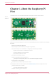
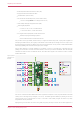

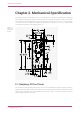
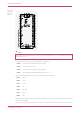
Table Of Contents
•
External Quad-SPI Flash with eXecute In Place (XIP)
•
High performance full-crossbar bus fabric
•
On-board USB1.1 (device or host)
•
30 multi-function General Purpose IO (4 can be used for ADC)
◦
1.8-3.3V IO Voltage (NOTE Pico IO voltage is fixed at 3.3V)
•
12-bit 500ksps Analogue to Digital Converter (ADC)
•
Various digital peripherals
◦
2 × UART, 2 × I2C, 2 × SPI, 16 × PWM channels
◦
1 × Timer with 4 alarms, 1 × Real Time Counter
•
2 × Programmable IO (PIO) blocks, 8 state machines total
◦
Flexible, user-programmable high-speed IO
◦
Can emulate interfaces such as SD Card and VGA
Pico provides minimal (yet flexible) external circuitry to support the RP2040 chip (Flash, crystal, power supplies and
decoupling and USB connector). The majority of the RP2040 microcontroller pins are brought to the user IO pins on the
left and right edge of the board. Four RP2040 IO are used for internal functions - driving an LED, on-board Switched Mode
Power Supply (SMPS) power control and sensing the system voltages.
Pico has been designed to use either soldered 0.1" pin-headers (it is one 0.1" pitch wider than a standard 40-pin DIP
package) or can be used as a surface mountable 'module', as the user IO pins are also castellated. There are SMT pads
underneath the USB connector and BOOTSEL button, which allow these signals to be accessed if used as a reflow-
soldered SMT module.
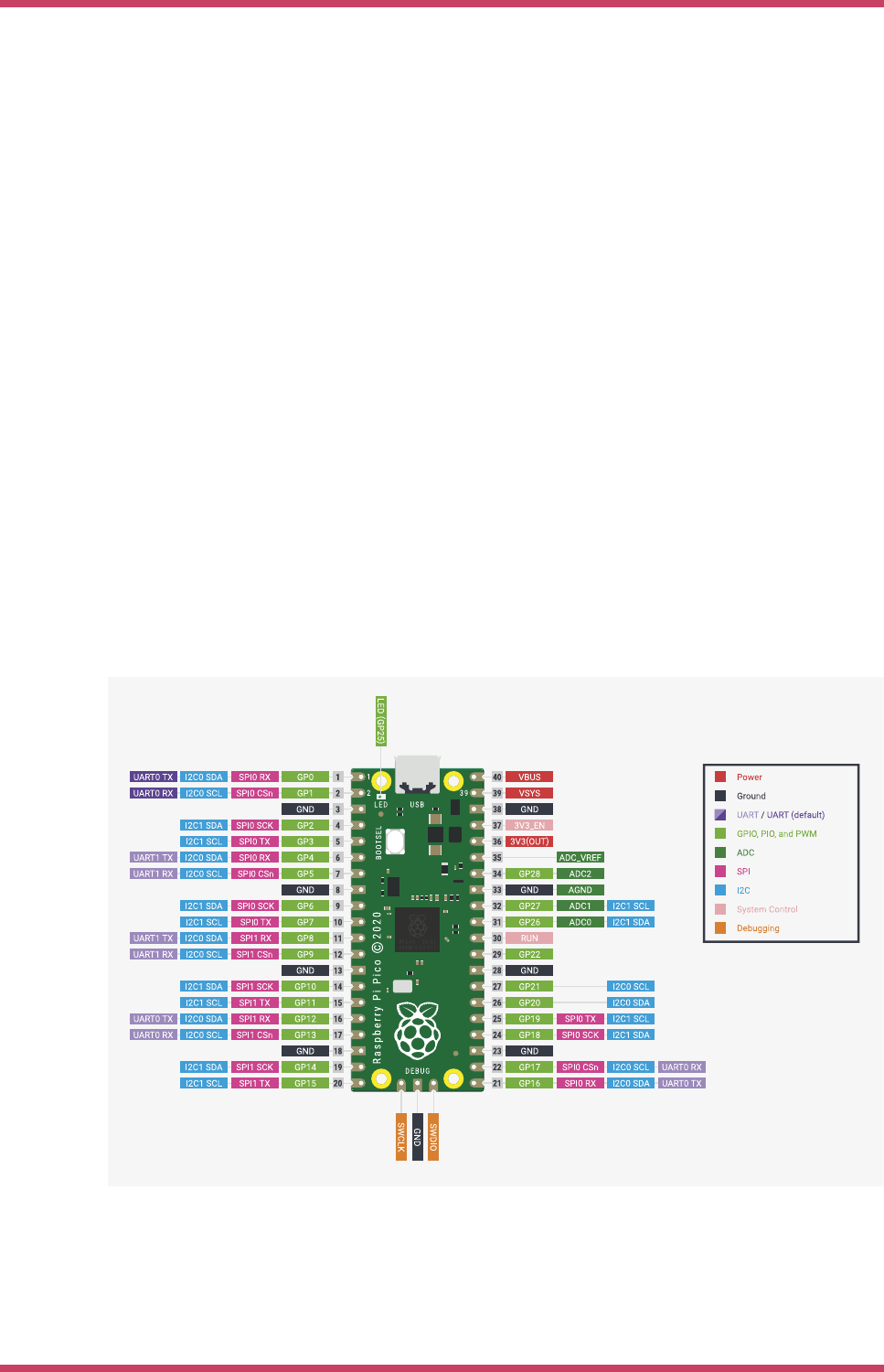
Figure 2. The pinout of
the Raspberry Pi Pico
Rev3 board.
Pico uses an on-board buck-boost SMPS which is able to generate the required 3.3 volts (to power RP2040 and external
circuitry) from a wide range of input voltages (~1.8 to 5.5V). This allows significant flexibility in powering the unit from
various sources such as a single Lithium-Ion cell, or 3 AA cells in series. Battery chargers can also be very easily
integrated with the Pico powerchain.
Reprogramming the Pico Flash can be done using USB (simply drag and drop a file onto the Pico which appears as a
Raspberry Pi Pico Datasheet
Chapter 1. About the Raspberry Pi Pico 4