
Datasheet
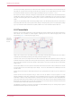
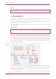
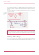
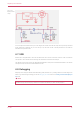


Table Of Contents
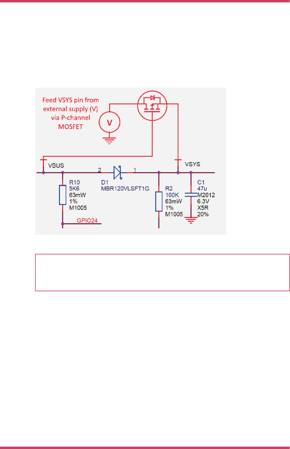
make sure the P-FET is turned on swiftly and with low resistance. When the input VBUS is removed, the P-FET will not
start to turn on until VBUS drops below the P-FETs Vt, meanwhile the body diode of the P-FET may start to conduct
(depending on whether Vt is smaller than the diode drop). For inputs that have a low minimum input voltage, or if the P-
FET gate is expected to change slowly (e.g. if any capacitance is added to VBUS) a secondary schottky diode across the
P-FET (in the same direction as the body diode) is recommended. This will reduce the voltage drop across the P-FETs
body diode.
An example of a suitable P-MOSFET for most situations is Diodes DMG2305UX which has a maximum Vt of 0.9V and Ron
of 100 milliohms (at 2.5V Vgs).
Figure 16. Raspberry
Pi Pico power ORing
using P channel
MOSFET.
CAUTION
If using Lithium-Ion cells they must have, or be provided with, adequate protection against over-discharge, over-charge,
charging outside allowed temperature range, and overcurrent. Bare, unprotected cells are dangerous and can catch
fire or explode if over-discharged, over-charged or charged / discharged outside their allowed temperature and/or
current range.
4.6. Using a Battery Charger
Pico can also be used with a battery charger. Although this is a slightly more complex use case it is still straightforward.
Figure 17 shows an example of using a 'Power Path' type charger (where the charger seamlessly manages swapping
between powering from battery or powering from the input source and charging the battery, as needed).
Raspberry Pi Pico Datasheet
4.6. Using a Battery Charger 20