
Datasheet
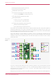
Table Of Contents
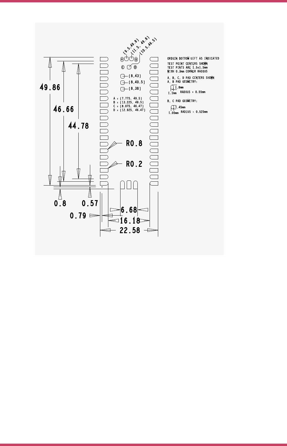
Figure 5. The SMT
footprint of the
Raspberry Pi Pico
Rev3 board.
The footprint shows the test point locations and pad sizes as well as the 4 USB connector shell ground pads (A,B,C,D).
The USB connector on Pico is a through-hole part, which provides it with mechanical strength. The USB socket pins do not
protrude all the way through the board, however solder does pool at these pads during manufacture and can stop the
module sitting completely flat. Hence we provide pads on the SMT module footprint to allow this solder to reflow in a
controlled manner when Pico goes through reflow again.
For test points that are not used, it is acceptable to void any copper under these (with suitable clearance) on the carrier
board.
2.3. Recommended Operating Conditions
Operating conditions for the Raspberry Pi Pico are largely a function of the operating conditions specified by its
components.
Operating Temp Max 85C (including self-heating)
Operating Temp Min -20C
VBUS 5V +/- 10%.
VSYS Min 1.8V
VSYS Max 5.5V
Raspberry Pi Pico Datasheet
2.3. Recommended Operating Conditions 9