
Datasheet

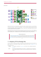
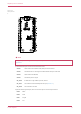
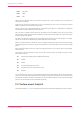
Table Of Contents

Figure 4. The pin
numbering of the Pico
W
NOTE
The physical pin numbering is shown in Figure 4. For pin allocation see Figure 2, or the full Pico W schematics in
Appendix B.
A few RP2040 GPIO pins are used for internal board functions:
GPIO29 OP/IP wireless SPI CLK/ADC mode (ADC3) to measure VSYS/3
GPIO25 OP wireless SPI CS - when high also enables GPIO29 ADC pin to read VSYS
GPIO24 OP/IP wireless SPI data/IRQ
GPIO23 OP wireless power on signal
WL_GPIO2 IP VBUS sense - high if VBUS is present, else low
WL_GPIO1 OP controls the on-board SMPS power save pin (Section 3.4)
WL_GPIO0 OP connected to user LED
Apart from GPIO and ground pins, there are seven other pins on the main 40-pin interface:
PIN40 VBUS
PIN39 VSYS
PIN37 3V3_EN
PIN36 3V3
Raspberry Pi Pico W Datasheet
2.1. Pico W pinout 8