
Datasheet


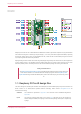

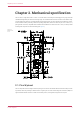
Table Of Contents

•
External Quad-SPI flash with eXecute In Place (XIP) and 16kB on-chip cache
•
High performance full-crossbar bus fabric
•
On-board USB1.1 (device or host)
•
30 multi-function general purpose I/O (four can be used for ADC)
◦
1.8-3.3V I/O voltage
•
12-bit 500ksps analogue to digital converter (ADC)
•
Various digital peripherals
◦
2 × UART, 2 × I2C, 2 × SPI, 16 × PWM channels
◦
1 × timer with 4 alarms, 1 × real time clock
•
2 × programmable I/O (PIO) blocks, 8 state machines in total
◦
Flexible, user-programmable high-speed I/O
◦
Can emulate interfaces such as SD card and VGA
NOTE
Raspberry Pi Pico W I/O voltage is fixed at 3.3V
Raspberry Pi Pico W provides a minimal yet flexible external circuitry to support the RP2040 chip: flash memory
(Winbond W25Q16JV), a crystal, power supplies and decoupling, and USB connector. The majority of the RP2040
microcontroller pins are brought to the user I/O pins on the left and right edge of the board. Four RP2040 I/O are used
for internal functions: driving an LED, on-board switch mode power supply (SMPS) power control, and sensing the
system voltages.
Pico W has an on-board 2.4GHz wireless interface using an Infineon CYW43439. The antenna is an onboard antenna
licensed from ABRACON (formerly ProAnt). The wireless interface is connected via SPI to the RP2040.
Pico W has been designed to use either soldered 0.1-inch pin-headers (it is one 0.1-inch pitch wider than a standard 40-
pin DIP package), or to be positioned as a surface-mountable 'module', as the user I/O pins are also castellated. There
are SMT pads underneath the USB connector and BOOTSEL button, which allow these signals to be accessed if used as
a reflow-soldered SMT module.
Raspberry Pi Pico W Datasheet
Chapter 1. About Raspberry Pi Pico W 4