
Datasheet

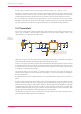
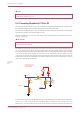
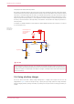
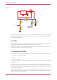
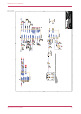
Table Of Contents

VBUS VSYS
W L_GPIO 2
R2
100 K
1%
M0 60 3
50 mW
C1
47u
6.3V
20 %
M2012
X5R
R10
10K
1%
M0 60 3
50 mW
D1
MBR120VLS FT1G
2 1
R1
10K
1%
M0 60 3
50 mW
3V3_E N
IN
Charger
OUT
BAT
+
Figure 9. Using Pico W
with a charger.
In the example we feed VBUS to the input of the charger, and we feed VSYS with the output via the previously mentioned
P-FET arrangement. Depending on your use case you may also want to add a Schottky diode across the P-FET as
described in the previous section.
3.7. USB
RP2040 has an integrated USB1.1 PHY and controller which can be used in both device and host mode. Pico W adds the
two required 27Ω external resistors and brings this interface to a standard micro-USB port.
The USB port can be used to access the USB bootloader (BOOTSEL mode) stored in the RP2040 boot ROM. It can also
be used by user code, to access an external USB device or host.
3.8. Wireless interface
Pico W contains an on-board 2.4GHz wireless interface using the Infineon CYW43439, which has the following features:
•
WiFi 4 (802.11n), Single-band (2.4 GHz)
•
WPA3
•
SoftAP (Up to 4 clients)
The antenna is an onboard antenna licensed from ABRACON (formerly ProAnt). The wireless interface is connected via
SPI to the RP2040.
Due to pin limitations, some of the wireless interface pins are shared. The CLK is shared with VSYS monitor, so only
when there isn’t an SPI transaction in progress can VSYS be read via the ADC. The Infineon CYW43439 DIN/DOUT and
IRQ all share one pin on the RP2040. Only when an SPI transaction isn’t in progress is it suitable to check for IRQs. The
interface typically runs at 33MHz.
For best wireless performance, the antenna should be in free space. For instance, putting metal under or close by the
antenna can reduce its performance both in terms of gain and bandwidth. Adding grounded metal to the sides of the
antenna can improve the antenna’s bandwidth.
Raspberry Pi Pico W Datasheet
3.7. USB 15