
Datasheet

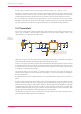
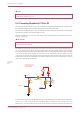
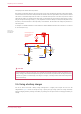
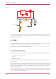
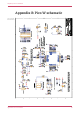
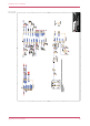
Table Of Contents

voltage-drop issues with the diode-only solution.
Note that the V
t
(threshold voltage) of the P-FET must be chosen to be well below the minimum external input voltage,
to make sure the P-FET is turned on swiftly and with low resistance. When the input VBUS is removed, the P-FET will not
start to turn on until VBUS drops below the P-FET’s V
t
, meanwhile the body diode of the P-FET may start to conduct
(depending on whether V
t
is smaller than the diode drop). For inputs that have a low minimum input voltage, or if the P-
FET gate is expected to change slowly (e.g. if any capacitance is added to VBUS) a secondary Schottky diode across
the P-FET (in the same direction as the body diode) is recommended. This will reduce the voltage drop across the P-
FET’s body diode.
An example of a suitable P-MOSFET for most situations is Diodes DMG2305UX which has a maximum V
t
of 0.9V and
R
on
of 100mΩ (at 2.5V V
gs
).
VBUS VSYS
W L_GPIO 2
R2
100 K
1%
M0 60 3
50 mW
C1
47u
6.3V
20 %
M2012
X5R
R10
10K
1%
M0 60 3
50 mW
D1
MBR120VLS FT1G
2 1
R1
10K
1%
M0 60 3
50 mW
3V3_E N
V
Feed VSYS pin f rom
external supply (V)
via P-channel
MOSFET
Figure 8. Pico W
power ORing using P
channel MOSFET.
CAUTION
If using Lithium-Ion cells they must have, or be provided with, adequate protection against over-discharge, over-
charge, charging outside allowed temperature range, and overcurrent. Bare, unprotected cells are dangerous and can
catch fire or explode if over-discharged, over-charged or charged / discharged outside their allowed temperature
and/or current range.
3.6. Using a battery charger
Pico W can also be used with a battery charger. Although this is a slightly more complex use case it is still
straightforward. Figure 9 shows an example of using a 'power path' type charger (where the charger seamlessly
manages swapping between powering from battery or powering from the input source and charging the battery, as
needed).
Raspberry Pi Pico W Datasheet
3.6. Using a battery charger 14