Raspberry Pi Pico W Datasheet Colophon Copyright © 2022 Raspberry Pi Ltd The documentation of the RP2040 microcontroller is licensed under a Creative Commons Attribution-NoDerivatives 4.0 International (CC BY-ND). build-date: 2022-06-29 build-version: 56f97ea-clean About the SDK Throughout the text "the SDK" refers to our Raspberry Pi Pico SDK. More details about the SDK can be found in the Raspberry Pi Pico C/C++ SDK book.
Raspberry Pi Pico W Datasheet Table of contents Colophon . . . . . . . . . . . . . . . . . . . . . . . . . . . . . . . . . . . . . . . . . . . . . . . . . . . . . . . . . . . . . . . . . . . . . . . . . . . . . . . . . . . . . . . . . . . . . . 1 Legal disclaimer notice . . . . . . . . . . . . . . . . . . . . . . . . . . . . . . . . . . . . . . . . . . . . . . . . . . . . . . . . . . . . . . . . . . . . . . . . . . . . . . . 1 1. About Raspberry Pi Pico W . . . . . . . . . . . . . . . . . . . . . . . . . .
Raspberry Pi Pico W Datasheet Chapter 1. About Raspberry Pi Pico W Raspberry Pi Pico W is a microcontroller board based on the Raspberry Pi RP2040 microcontroller chip. Figure 1. The Raspberry Pi Pico W Rev3 board. Raspberry Pi Pico W has been designed to be a low cost yet flexible development platform for RP2040, with a 2.4GHz wireless interface and the following key features: • RP2040 microcontroller with 2MB of flash memory • On-board single-band 2.4GHz wireless interfaces (802.
Raspberry Pi Pico W Datasheet • External Quad-SPI flash with eXecute In Place (XIP) and 16kB on-chip cache • High performance full-crossbar bus fabric • On-board USB1.1 (device or host) • 30 multi-function general purpose I/O (four can be used for ADC) ◦ 1.8-3.
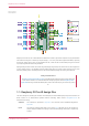
Raspberry Pi Pico W Datasheet Figure 2. The pinout of the Pico W Rev3 board Raspberry Pi Pico W uses an on-board buck-boost SMPS which is able to generate the required 3.3V (to power RP2040 and external circuitry) from a wide range of input voltages (~1.8 to 5.5V). This allows significant flexibility in powering the unit from various sources, such as a single lithium-ion cell, or three AA cells in series. Battery chargers can also be very easily integrated with the Pico W powerchain.
Raspberry Pi Pico W Datasheet STEP 3D A STEP 3D model of Raspberry Pi Pico W, for 3D visualisation and fit-check of designs which include Pico W as a module, can be found here. Fritzing A Fritzing part for use in e.g. breadboard layouts can be found here. Permission to use, copy, modify, and/or distribute this design for any purpose with or without fee is hereby granted.
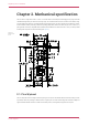
Raspberry Pi Pico W Datasheet Chapter 2. Mechanical specification The Pico W is a single sided 51mm × 21mm × 1mm PCB with a micro USB port overhanging the top edge, and dual castellated/through-hole pins around the two long edges. The onboard wireless antenna is located on the bottom edge. To avoid detuning the antenna, no material should intrude into this space.
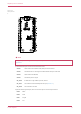
Raspberry Pi Pico W Datasheet Figure 4. The pin numbering of the Pico W NOTE The physical pin numbering is shown in Figure 4. For pin allocation see Figure 2, or the full Pico W schematics in Appendix B.
Raspberry Pi Pico W Datasheet PIN35 ADC_VREF PIN33 AGND PIN30 RUN VBUS is the micro-USB input voltage, connected to micro-USB port pin 1. This is nominally 5V (or 0V if the USB is not connected or not powered). VSYS is the main system input voltage, which can vary in the allowed range 1.8V to 5.5V, and is used by the on-board SMPS to generate the 3.3V for the RP2040 and its GPIO. 3V3_EN connects to the on-board SMPS enable pin, and is pulled high (to VSYS) via a 100kΩ resistor. To disable the 3.
Raspberry Pi Pico W Datasheet Figure 5. The SMT footprint of the Pico W Rev3 board. The footprint shows the test point locations and pad sizes as well as the 4 USB connector shell ground pads (A,B,C,D). The USB connector on Pico W is a through-hole part, which provides it with mechanical strength. The USB socket pins do not protrude all the way through the board, however solder does pool at these pads during manufacture and can stop the module sitting completely flat.
Raspberry Pi Pico W Datasheet Chapter 3. Applications information 3.1. Programming the flash The on-board 2MB QSPI flash can be (re)programmed either using the serial wire debug port or by the special USB mass storage device mode. The simplest way to reprogram the Pico W’s flash is to use the USB mode. To do this, power-down the board, then hold the BOOTSEL button down during board power-up (e.g. hold BOOTSEL down while connecting the USB). The Pico W will then appear as a USB mass storage device.
Raspberry Pi Pico W Datasheet the shunt reference will draw continuous current through the 200Ω filter resistor (3.3V - 3.0V)/200 = ~1.5mA. Note that the 1Ω resistor on Pico W (R9) is designed to help with shunt references that would otherwise become unstable when directly connected to 2.2μF. It also ensures there is filtering even in the case that 3.3V and ADC_VREF are shorted together (which users who are tolerant to noise and want to reduce the inherent offset may wish to do).
Raspberry Pi Pico W Datasheet NOTE The RP2040 has an on-chip linear regulator (LDO) that powers the digital core at 1.1V (nominal) from the 3.3V supply, which is not shown in Figure 6. 3.5. Powering Raspberry Pi Pico W The simplest way to power Pico W is to plug in the micro-USB, which will power VSYS (and therefore the system) from the 5V USB VBUS voltage, via D1 (so VSYS becomes VBUS minus the Schottky diode drop).
Raspberry Pi Pico W Datasheet voltage-drop issues with the diode-only solution. Note that the Vt (threshold voltage) of the P-FET must be chosen to be well below the minimum external input voltage, to make sure the P-FET is turned on swiftly and with low resistance. When the input VBUS is removed, the P-FET will not start to turn on until VBUS drops below the P-FET’s Vt, meanwhile the body diode of the P-FET may start to conduct (depending on whether Vt is smaller than the diode drop).
Raspberry Pi Pico W Datasheet Figure 9. Using Pico W with a charger. IN OUT Cha rger BAT + D1 VBUS 2 R10 10K 50 mW 1% M0 60 3 1 MBR120V LS FT1G VSYS R2 100 K 50 mW 1% M0 60 3 C1 47u M2012 6.3V X5 R 20 % W L_GPIO 2 R1 10K 50 mW 1% M0 60 3 3V3_E N In the example we feed VBUS to the input of the charger, and we feed VSYS with the output via the previously mentioned P-FET arrangement.
Raspberry Pi Pico W Datasheet There are three GPIO pins from the CYW43439 that are used for other board functions and can easily be accessed via the SDK: WL_GPIO2 IP VBUS sense - high if VBUS is present, else low WL_GPIO1 OP controls the on-board SMPS power save pin (Section 3.4) WL_GPIO0 OP connected to user LED NOTE Full details of the Infineon CYW43439 can be found in the datasheet. 3.9. Debugging Pico W brings the RP2040 serial wire debug (SWD) interface to a three-pin debug header.
Raspberry Pi Pico W Datasheet Appendix A: Availability Raspberry Pi guarantee availability of the Raspberry Pi Pico W product until at least January 2028. Support For support see the Pico section of the Raspberry Pi website, and post questions on the Raspberry Pi forum. Ordering code Table 1. Part Number Model Order Code EAN Minimal Order RRP Quantity Raspberry Pi Pico W SCO918 5056561803173 1+ pcs / Bulk US$6.00 Raspberry Pi Pico WH SCO919 5056561800196 1+ pcs / Bulk US$7.
Raspberry Pi Pico W Datasheet Appendix B: Pico W schematic Figure 10. The Pico W Rev3 board schematic.
Raspberry Pi Pico W Datasheet Figure 11. The Pico W Rev3 board schematic.
Raspberry Pi Pico W Datasheet Appendix C: Pico W component locations Figure 12. The Pico W Rev3 board component locations.
Raspberry Pi Pico W Datasheet Appendix D: Documentation release history Table 2. Documentation release history Release Date Description 1.0 30 Jun 2022 Initial release The latest release can be found at https://datasheets.raspberrypi.com/picow/pico-w-datasheet.pdf.