
Datasheet
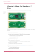
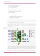
Table Of Contents
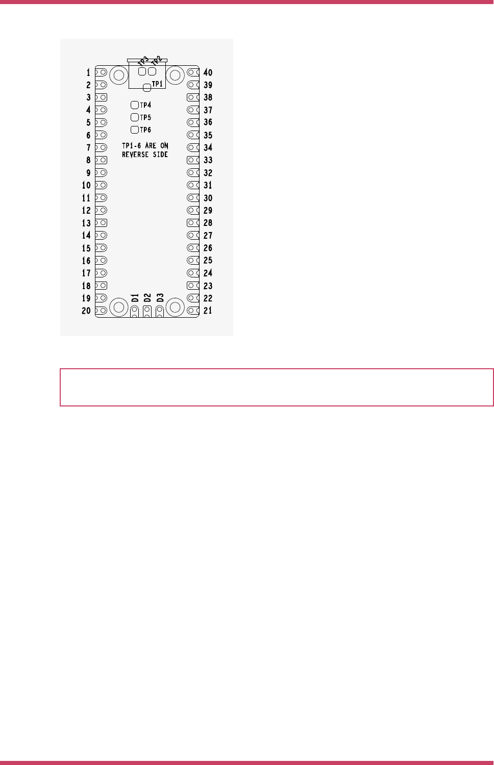
Figure 4. The pin
numbering of the
Raspberry Pi Pico
Rev3 board.
NOTE
The physical pin numbering is shown in Figure 4, for the pin allocation see Figure 2 or the full Raspberry Pi Pico
schematics in Appendix B.
A few RP2040 GPIO pins are used for internal board functions, these are:
GPIO29 IP Used in ADC mode (ADC3) to measure VSYS/3
GPIO25 OP Connected to user LED
GPIO24 IP VBUS sense - high if VBUS is present, else low
GPIO23 OP Controls the on-board SMPS Power Save pin (Section 4.4)
Apart from GPIO and ground pins, there are 7 other pins on the main 40-pin interface:
PIN40 VBUS
PIN39 VSYS
PIN37 3V3_EN
PIN36 3V3
PIN35 ADC_VREF
PIN33 AGND
PIN30 RUN
VBUS is the micro-USB input voltage, connected to micro-USB port pin 1. This is nominally 5V (or 0V if the USB is not
connected or not powered).
VSYS is the main system input voltage, which can vary in the allowed range 1.8V to 5.5V, and is used by the on-board
Raspberry Pi Pico Datasheet
2.1. Raspberry Pi Pico Pinout 7