
Datasheet
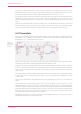
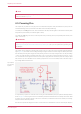
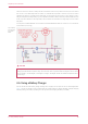


Table Of Contents
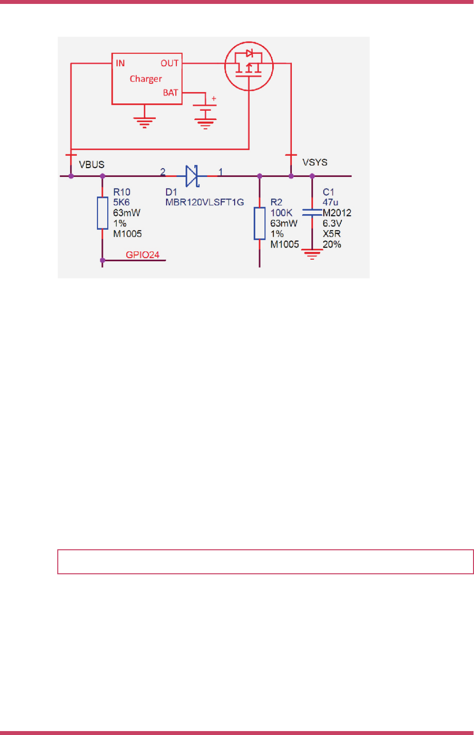
Figure 17. Using
Raspberry Pi Pico with
a charger.
In the example we feed VBUS to the input of the charger, and we feed VSYS with the output via the previously mentioned
P-FET arrangement. Depending on your use case you may also want to add a schottky diode across the P-FET as
described in the previous section.
4.7. USB
RP2040 has an integrated USB1.1 PHY and controller which can be used in both Device and Host mode. Pico adds the
two required 27 ohm external resistors and brings this interface to a standard micro-USB port.
The USB port can be used to access the USB bootloader (BOOTSEL mode) stored in the RP2040 boot ROM. It can also be
used by user code, to access an external USB device or host.
4.8. Debugging
Raspberry Pi Pico brings the RP2040 Serial Wire Debug (SWD) interface to a 3 pin debug header on the lower edge of the
board. To get started using the debug port see the Debugging with SWD section in the Getting started with Raspberry Pi
Pico book.
NOTE
The RP2040 chip has internal pull up resistors on the SWDIO and SWCLK pins, both nominally 60 kOhm.
Raspberry Pi Pico Datasheet
4.7. USB 21