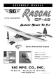
Wingspan: 49 in. (1245 mm) Wing Area: 324 sq.in. (20.9 dm2) Length: 32-1/2 in. (825.5 mm) Flying Weight: 22 - 25 oz. (624 - 700 g) Wing Loading: 9.7 - 11.1 oz./sq.ft. (30 - 33 g/dm2) Radio Req.: 4 Channel, Mini Receiver, 4 Mini Servos © Copyright 2012, SIG Mfg. Co., Inc.
In addition to providing the critical charging profile needed to safely charge lipo batteries, a lipo battery charger also includes the capability of "balancing" the available voltage in the cells, ensuring that the battery pack is at peak capacity at the end of the charge cycle. This translates to better flight times and a longer life from the battery pack.
❑ ❑ ❑ ❑ ❑ ❑ ❑ ❑ When exposed to drier air, the wood loses the excess moisture, dimensionally shrinking microscopically in the process. That's all it takes to cause some slight relaxing of the covering, causing wrinkles to appear. Any wrinkles that appear in the covering are easy to remove by applying a little heat from a small modeler's heat iron. Because of this model's small size, we do not recommend using a heat gun to tighten up loose covering. A typical hobby type covering iron will work just fine.
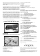
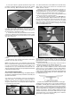
❑ 1) For maximum strength, we recommend using SIG Epoxy Glue for joining the wing panels in this step. a) Trial fit both wing panels together, without glue, on the plywood wing joiner to familiarize yourself with the assembly. Then, take back apart. b) Mix up a small amount of epoxy glue. Use a wire or stick to quickly coat the inside of the wing joiner slot in the end of the right wing panel. Also, coat the right half of the plywood wing joiner with glue.
of scrap wood in the round hole near the center of the wing. This string is used to pull the aileron servo chord through the wing, from the servo mount towards the center section, in the following steps. ❑ 6) In this step we will install a Nylon Control Horn on the bottom of each aileron. Make sure the horn is directly in line with the servo arm, and that the base of the horn is right at the front edge of the aileron. Follow these steps.
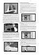
❑ 9) Note that the bottom of the stabilizer is the side without any white covering. Mount a nylon control horn on the bottom of the RIGHT elevator, as follows: a) Two holes are pre-drilled in the right elevator, under the covering material, for the control horn mounting. Puncture the covering material directly over these two holes, on the BOTTOM of the elevator only, to accept the two pegs of the control horn.
❑ 12) Glue the tailwheel assembly in place in the leading edge of the rudder. ❑ 13) Mount a nylon control horn on the left side of the rudder. a) Shorten the pegs on the bottom of the control horn like you did for the elevator horn back in Step 8. b) Two holes are pre-drilled in the bottom of the rudder for the control horn mounting.
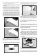
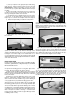
ELEVATOR & RUDDER HOOKUP For this section you will need the Fuselage, (2) Servos, (2) Long Formed Wire Pushrods, and (2) Nylon Pushrod Keepers. ❑ 16) Mount the elevator and rudder servos in the fuselage, using the screws that came with the servos. a) Begin by positioning the servos in place in the plywood servo tray built into the fuselage. Make sure the ends of the servo arms line up with the plastic pushrod tubes already installed in the fuselage.
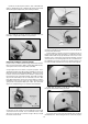
c) Use a pair of pliers to firmly grasp the pushrod wire at the mark just made, and then bend the plain end of the wire 90O DOWNWARDS (so that the pushrod wire comes into the control horn from the top - see photo below). Make the bend as sharp as possible. d) The excess length of pushrod wire can now be cutoff, leaving about a 3/16" end leg to pass through the control horn hole. Use a good sharp pair of wire cutters to do this.
c) Remove the wheel pants from the axles. Drill .046” dia. (3/46” or #56 bit) pilot holes completely through the wheel pant wall and the plywood pad inside, at the marks just made. ❑ 22) Assemble the wheel pants and wheels simultaneously onto their axles, using the M2 x 5.5mm screws provided. ❑ 25) Using (3) M2 x 6 mm PWA Screws, mount the aluminum motor mount to the firewall. a) First mark the locations for the three mounting screws on the face of the firewall. Notice that there is a 5/16” dia.
the first time, we suggest removing them and "hardening" the threads in the plywood with a drop of thin CA glue. Once the glue has set, put the mount back in place and tighten the screws firmly. RECEIVER & BATTERY INSTALLATION For this section, you will need the remainder of hook-and-loop tape, your receiver, the aileron Y-Harness, and a charged flight battery pack. ❑ 26) Reinstall the brushless motor into the motor mount. Insert the back end of the motor shaft into the mount, and then use a 1.
SYSTEM TESTS The completed radio and motor systems can now be powered up, then tested and adjusted for proper operation. Note that the wing and propeller are NOT yet installed at this point. ❑ 33) Make sure the aileron, elevator, and rudder trim levers on your transmitter are each in neutral position and that the throttle stick is in the full "low throttle" position. a) Turn on your transmitter. NOTE: The transmitter MUST ALWAYS be turned on first and turned off last! b) Plug the battery pack into the ESC.
MOUNTING THE PROPELLER & SPINNER ❑ 40) Locate the Propeller with Brass Hex Nut and Aluminum Sleeve, plus the rubber Spinner from the kit contents. a) Remove the front M3 lock nut and the washer from the motor shaft. Then thread the Brass Hex Nut that came with the propeller onto the motor shaft. Thread it all the way back, up tight against the rear lock nut. Tighten it securely. (If you have some Locktite® thread locking compound, put a drop between the two nuts before you tighten them together.
tion, even when the transmitter is in storage. Be sure to recheck the throttle stick position before plugging in the battery pack. Under no circumstances should you hold this model by the nose when the battery is plugged in. Never plug your battery pack onto the system until; 1) your transmitter is ON with the throttle stick in the low position, and 2) you are on the flight line, ready to fly.
AN INSTRUCTOR CAN SAVE YOUR AIRPLANE! If you are new to the hobby of flying R/C model airplanes, DO NOT attempt to fly this model by yourself! We strongly urge you to seek the help of a competent flight instructor. There are hundreds of R/C clubs in the U.S. and these clubs normally have designated instructors, who are eager to help newcomers. The easiest way to find an R/C flying club in your area is to ask your local hobby shop or check the AMA (Academy of Model Aeronautics) web site: www.modelaircraft.
WARNING! THIS IS NOT A TOY! CUSTOMER SERVICE Flying machines of any form, either model-size or full-size, are not toys! Because of the speeds that airplanes must achieve in order to fly, they are capable of causing serious bodily harm and property damage if they crash.