User Manual C UL US 1F61 I.T.E. LISTED Copyright ©2005 Raritan Computer, Inc. USTIP-0C-E June 2005 255-31-0006 Raritan Computer Inc. 400 Cottontail Lane Somerset, NJ 08873 USA Tel. 1-732-764-8886 Fax. 1-732-764-8887 E-mail: sales@raritan.com http://www.raritan.com/ Raritan Computer Europe, B.V. Eglantierbaan 16 2908 LV Capelle aan den IJssel The Netherlands Tel. 31-10-284-4040 Fax. 31-10-284-4049 E-mail: sales.europe@raritan.com http://www.raritan.com/ Raritan Computer Japan, Inc. 4th Flr.
FCC Information This equipment has been tested and found to comply with the limits for a Class A digital device, pursuant to Part 15 of the FCC Rules. These limits are designed to provide reasonable protection against harmful interference in a commercial installation. This equipment generates, uses, and can radiate radio frequency energy and if not installed and used in accordance with the instructions, may cause harmful interference to radio communications.
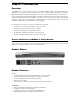
Login • • • • The default UST-IP login user name is admin, and the default password is raritan. This user has administrative privileges. Passwords are case sensitive and must be entered in the exact case combination in which they were created. The default password raritan must be entered entirely in lowercase letters. To ensure security, change the default password as soon as possible. Default IP Address • UST-IP ships with the default IP address of 192.168.0.
Contents Chapter 1: Introduction .................................................................. 1 Overview ....................................................................................................................................1 Access via Internet, LAN/WAN, or dial-up Modem..............................................................1 Product Photos...........................................................................................................................1 Product Features..
Time and Date..........................................................................................................................37 Access Control List ..................................................................................................................38 Remote Syslog.........................................................................................................................39 View UST-IP Status .................................................................................
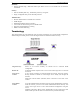
CHAPTER 1: INTRODUCTION 1 Chapter 1: Introduction Overview Congratulations on your purchase of UST-IP, the industry-leading solution for multi-platform, highperformance, network-based, remote KVM console access. UST-IP enables highly-secure, multi-user, bandwidth-efficient, and software-independent access to your servers’ KVM consoles via a web browser.
2 UST-IP USER MANUAL Reliability • External modem using a dedicated modem port allows servers to be accessible even if network is unavailable Security • • SSL 128-bit RSA public key, 128-bit RC4 private key encryption Single, configurable TCP port for firewall protection Administration • • • • • • Remote Administration via Web Browser interface SNMP Support Simplified installation and user interface User console for direct analog access to KVM switch Extensive downloadable user event log DHCP or fixe
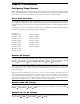
CHAPTER 2: INSTALLATION 3 Chapter 2: Installation Configuring Target Servers Before installing UST-IP, first configure any target servers that you wish to access via UST-IP, in order to ensure optimum performance, as outlined below. Note that the following configuration requirements apply only to target servers, not to the computers that you will be using to access UST-IP remotely.
4 UST-IP USER MANUAL Linux Settings On target servers running Linux graphical interfaces, set the mouse acceleration to exactly 1 and set threshold to exactly 1. As mentioned above, please ensure that each target server running Linux is using a resolution supported by UST-IP at a standard VESA resolution and refresh rate. Each Linux target server should also be set so the blanking times are within +/- 40% of VESA standard values.
CHAPTER 2: INSTALLATION 5 Apple Macintosh Settings For target servers running an Apple Macintosh operating system, while using UST-IP to access and control your target server, you must set the UST-IP client (Raritan Remote Client) to “single cursor” mode. Dual cursor mode is not supported, and the two mouse pointers will not appear in sync if you attempt to control a Macintosh server via UST-IP in dual cursor mode.
6 UST-IP USER MANUAL Initial Configuration During initial configuration, the UST-IP Setup Wizard helps you quickly set up UST-IP for the first time. The UST-IP Setup Wizard appears only when accessing the Administrative Menus on an unconfigured UST-IP, and guides you through initial configuration parameters. The easiest way to perform this initial configuration is by using the Local Admin Console (see ‘Physical Connection’ instructions in the previous sections). 1.
CHAPTER 2: INSTALLATION 7 ♦ YES: Enables dynamic IP addressing for UST-IP. Each time UST-IP boots, it requests an IP address from the local DHCP server. Note that this setting can make remote access to UST-IP from outside the LAN difficult, since the dynamically assigned IP address must be known in order to initiate a connection. ♦ NO (default): Assigns a fixed IP address to the UST-IP unit (recommended). IP Address: Enter the IP address for UST-IP given by your Network Administrator.
8 UST-IP USER MANUAL Connect to UST-IP Remotely Having completed the physical installation of UST-IP, you are now ready to establish an initial network connection. Below are basic instructions for doing so. Please see Chapter 3: Raritan Remote Client for detailed instructions, being sure to review the “Remote KVM Console Control” and “Color Calibration” sections to optimize your UST-IP performance. Launch Raritan Remote Client (RRC) 1. Log into any Windows-based computer with network access to UST-IP. 2.
CHAPTER 2: INSTALLATION 9 Establish a Connection Upon launching the Raritan Remote Client (RRC), UST-IP will request your user credentials. Log on with the default username and password (admin and raritan). You will connect to your UST-IP unit. Use the RRC Navigator, found on the left-hand side of the RRC window, to select and connect to a port. Click on “Synchronize Mouse” to converge the mouse pointers displayed. The RRC Toolbar provides single-click access to RRC’s most frequently-used features.
10 UST-IP USER MANUAL
CHAPTER 3: RARITAN REMOTE CLIENT 11 Chapter 3: Raritan Remote Client Invoking Raritan Remote Client (RRC) via Web Browser UST-IP features Web Browser access, providing a connection from any Windows-based Remote PC running Microsoft Internet Explorer 4.0+, Mozilla 1.1+, and Netscape 7+.
12 UST-IP USER MANUAL 3. Depending on your browser’s security configuration, you may see any or all of the following dialog boxes, confirming the access and launch of an externally-provided program. Click Yes to advance through any of these prompts. Note: Microsoft Windows 2000 and Microsoft Windows XP restrict certain types of users from downloading and running ActiveX controls and plug-ins, regardless of the settings in Internet Explorer and regardless of your approval of the above warnings.
CHAPTER 3: RARITAN REMOTE CLIENT 13 Optional: Installing Raritan Remote Client Software Note: This step is optional. UST-IP can be accessed from a Remote PC either by installing RRC software, or by launching RRC via web browser (see previous section). Accessing UST-IP via web browser does not require any software installation on the Remote PC. 1. Insert the provided RRC CD-ROM into the CD-ROM drive of your PC. 2. The RRC setup program will run automatically.
14 UST-IP USER MANUAL RRC Navigator The RRC Navigator provides a single view to every known Raritan device, allowing convenient access to multiple Raritan networked appliances. The RRC Navigator displays: • All Raritan devices for which a connection profile exists • All Raritan devices that are automatically identified on the network Note: Automatic Raritan device identification uses UDP protocol, and will usually identify all Raritan devices on your subnet.
CHAPTER 3: RARITAN REMOTE CLIENT 15 Navigator Options Certain RRC Navigator attributes may be customized to your preferences. Display / Hide Navigator – Toggle whether the RRC Navigator is shown. This option can also be toggled by choosing View → Navigator from the Menu Bar. Refresh Navigator – Update the device status information shown in the RRC Navigator.
16 UST-IP USER MANUAL • Modem: Select the modem, as configured in Windows, which RRC should use to dial and connect to your Raritan device. Select a TCP Port to use: • Use Default Port Number: UST-IP is configured by default to use TCP Port 5000 for communicating with RRC. UST-IP can be configured to use a different TCP Port (see Chapter 4: Administrative Functions, Network Configuration); if so, uncheck the Use Default Port Number option, and enter the configured TCP Port to be used. 5.
CHAPTER 3: RARITAN REMOTE CLIENT 17 Establishing a New Connection To connect to a Raritan networked device, simply double-click on its entry in the RRC Navigator. You will be asked to authenticate the device. Note: The default UST-IP login user name is admin, with the password raritan. This user has administrative privileges. Passwords are case sensitive and must be entered in the exact case combination in which they were created. The default password raritan must be entered entirely in lowercase letters.
18 UST-IP USER MANUAL RRC Toolbar and Shortcuts The RRC Toolbar provides convenient, one-click access to the most commonly used features and parameters of Raritan Remote Client: BUTTON BUTTON NAME HOTKEY FUNCTION New Profile Creates a new Navigator entry for a Raritan device; same results as selecting Connection New Profile in the menu bar.
CHAPTER 3: RARITAN REMOTE CLIENT 19 RRC Status Bar The Status Bar at the bottom of the Raritan Remote Client window conveys information about the status of your remote connection session to UST-IP. Bandwidth Usage Indicator Video Sensing Status Connections Indicator Security Indicator Lock Key Indicators Video Sensing Status Indicates the occurrence of video sensing that reflects a counter until the video actually appears. This matches what the user sees on the screen.
20 UST-IP USER MANUAL Remote KVM Console Control After using the RRC Navigator to establish a connection with an UST-IP unit (see the previous section: Establishing a New Connection), the Navigator entry corresponding to the UST-IP unit will expand to show all ports on the UST-IP enabled for remote access. To establish a remote KVM console connection, simply double-click on the KVM path that you would like to control.
CHAPTER 3: RARITAN REMOTE CLIENT 21 Single Mouse Mode / Dual Mouse Mode When remotely viewing a Target Server that uses a pointing device, by default you will see two mouse pointers within the Remote Desktop area of the Raritan Remote Client window. The Raritan Remote Client mouse pointer, generated by the operating system on which RRC is running, slightly leads the Target Server's mouse pointer during movement, a necessary result of digital delay.
22 UST-IP USER MANUAL Keyboard Macros RRC allows users to create custom keyboard macros in order to send given key sequences to the remote server or KVM switch connected to UST-IP. This feature allows customers to send keystrokes to remote servers that may be otherwise unintentionally interpreted by the computer on which RRC is running. UST-IP’s Keyboard Macro feature can be used to ensure that keystroke combinations intended for the Target Server are sent to, and interpreted only by, the Target Server.
CHAPTER 3: RARITAN REMOTE CLIENT 23 3. The Add Keyboard Macro dialog box opens. 4. Build the Keyboard Macro by editing all the fields in the Add Keyboard Macro window, in the order described below. Click OK when finished. a. Enter a name into the Keyboard Macro Name field, which will appear on the RRC Menu Bar, after successful creation of the keyboard macro. For our example, "Minimize All Windows". b.
24 UST-IP USER MANUAL 5. After clicking OK, the Keyboard Macros dialog box will appear, listing your new keyboard macro. 6. Click Close to complete the keyboard macro editing procedure. Running a Keyboard Macro Once a macro is created, it can be run via the RRC Menu Bar or with the hotkey combination if one had been designated during the macro creation. Menu Bar Activation After a macro has been created, it appears in the Keyboard menu on the RRC Menu Bar.
CHAPTER 3: RARITAN REMOTE CLIENT 25 Connection and Video Properties UST-IP's dynamic video compression algorithms maintain KVM console usability under varying bandwidth constraints. Unlike competitive solutions, UST-IP optimizes its KVM output for not only LAN utilization, but also via the WAN and dial-up. By dynamically adjusting color depth and limiting video output, UST-IP offers the optimal balance between video quality and system responsiveness in any bandwidth constraint.
26 UST-IP USER MANUAL Internet Flow Control Many public WAN links are by their very nature unpredictable. Packets sent over the public Internet do not necessarily arrive at their destination in the order they were sent. When using UST-IP over an unpredictable public WAN (particularly in international scenarios), the Internet Flow Control toggle ensures that packets transmitted by UST-IP are received and reconstructed by RRC in the correct order.
CHAPTER 3: RARITAN REMOTE CLIENT 27 Analog-to-Digital Settings The following parameters are best left to UST-IP to automatically detect (on the RRC Menu Bar, select Video > Auto-sense Video Settings), but a brief description of each is included here. • PLL Settings: If the video image looks extremely blurry or unfocused, the PLL Settings for clock and phase can be adjusted until a better image appears on the active Target Server. - Clock: Horizontal sync divider to produce pixel clock.
28 UST-IP USER MANUAL Color Calibration Automatic Color Calibration adjusts the color settings on UST-IP to reduce excess color noise and data during digitization of video images. This data streamlining will increase the operational performance of UST-IP, particular color accuracy. A very simple procedure to execute, Color Calibration should be performed if the color levels (hue, brightness, saturation) of transmitted video images do not seem accurate.
CHAPTER 3: RARITAN REMOTE CLIENT 29 Remote Device Administration When logged into an UST-IP unit as a user with administrative privileges, UST-IP allows you to perform many powerful device administration tasks remotely. Configuration Menus An Administrative user can access UST-IP's lowest level configuration menus (explained in detail in Chapter 4), by double-clicking the "Admin" port entry of an UST-IP device shown in the RRC Navigator.
30 UST-IP USER MANUAL
CHAPTER 4: ADMINISTRATIVE FUNCTIONS 31 Chapter 4: Administrative Functions Accessing the Administrative Functions Access and execute Administrative functions via local admin console, or via remote administration. Only administrators (users with administrative privileges) can access the UST-IP Administrative Menus. Local Admin Console Power ON the UST-IP unit via the power switch on the back of the unit. Note: The default UST-IP login user name is admin, with the password raritan.
32 UST-IP USER MANUAL Remote Admin Console An alternative way to access UST-IP’s administrative functions is to do so remotely, using the Raritan Remote Client. Any administrative user logged on to UST-IP at a Remote PC can perform administrative functions remotely to make changes to the system, as long as UST-IP is set to allow remote administration privileges – see Allow Remote Administration on the Security Configuration screen.
CHAPTER 4: ADMINISTRATIVE FUNCTIONS 33 Network Configuration Please note that after you have made changes to the Network Configuration, you must press Ctrl+S to save your changes. Reboot after all changes are saved to apply them to your Network. • Name: Designate a unique name for this UST-IP unit, for example, “Miami Data Center.” The default name is UST-IP. • Enable Ethernet Interface: Designates whether UST-IP should enable its Ethernet adapter as active (default: YES).
34 UST-IP USER MANUAL User Station Options In the User Station Configuration screen, use the and favor None, Remote, or Local users: • • • arrows on your keyboard to set Port Priority to If you set Port Priority to Remote, a Remote user will automatically terminate a Local user session when attempting to connect to the same USTIP unit. If you set Port Priority to Local, a Local user will automatically terminate a Remote user session when attempting to connect to the same USTIP unit.
CHAPTER 4: ADMINISTRATIVE FUNCTIONS - 35 authentication. After authentication, KVM data is also transferred with 128-bit encryption, but using a proprietary protocol more efficient than SSL. SSL authentication, SSL data encryption: This mode secures user names and passwords, and provides high-level security for KVM data. 128-bit Secure Sockets Layer (SSL) protocol provides a private communications channel between UST-IP and the Remote PC during initial connection authentication.
36 UST-IP USER MANUAL Performance Settings The Performance Settings screen is used to set up UST-IP’s video data transfer and bandwidth parameters. • Pause video stream for idle users: Pausing the flow of video data during periods of prolonged inactivity will prevent an inactive user from needlessly consuming bandwidth. - Never (default): Video data will continually be sent to Remote PC, constantly updating the screen, even if the remote user is Idle, sending no active input to UST-IP.
CHAPTER 4: ADMINISTRATIVE FUNCTIONS 37 Time and Date Current Date and Time on the UST-IP unit are listed on this screen. Once saved, Time and Date changes will not take effect until UST-IP is restarted. • New Date / New Time: To manually input changes to current date and time values. • Adjust for daylight savings time: Toggle between YES and NO to reflect whether your country or state follows the daylight savings time procedure.
38 UST-IP USER MANUAL Access Control List Set UST-IP accessibility in the Access Control List (ACL) to allow or deny specific IP Addresses, or ranges of IP Addresses, from connecting to the UST-IP unit. If entering a range of IP Addresses, type the starting and the ending IP Address values in the Start and End columns; use the TAB key to navigate through the fields. Use the and keys to select Allow or Deny for each line item.
CHAPTER 4: ADMINISTRATIVE FUNCTIONS 39 Remote Syslog Use the Remote Syslog Configuration screen to allow remote users to save the server logs. Use the and keys to select Yes or No. If you select Yes, type the IP Adress to which you want to save the syslog in the Remote Syslog Server IP field, specify the information to save in Syslog Priority Threshold (for example, Notices, Debugs, Emergency messages, etc.), and select the category of data in the Syslog Category field.
40 UST-IP USER MANUAL View UST-IP Status The UST-IP Event Log screen shows a log file containing information about UST-IP log in and connection activities. This Event Log stores UST-IP events, such as user login or logout, bad login attempts, Admin login, and logout at the UST-IP Admin console, Admin changes to the system configuration, Admin user profile additions, changes, or deletions, modem activity, system startup and shutdown, and all errors that occur, with the date and time of each event.
CHAPTER 4: ADMINISTRATIVE FUNCTIONS 41 Diagnostics While navigating the Main Menu of the Administrative Console, pressing and will invoke the UST-IP Diagnostic functions. These functions are meant to enable Raritan Technical Support to assist you in the case of a problem with your UST-IP unit. Do not invoke these functions unless you are fully aware of their meanings and intended use. Please contact Raritan Technical Support should you require more information.
42 UST-IP USER MANUAL
APPENDIX A: SPECIFICATIONS 43 Appendix A: Specifications ITEM DIMENSIONS (WXDXH) WEIGHT POWER UST-IP1 1U 19” Rackmount Case: 17.2” (W) x 11.46” (D) x 1.72” (H) 440mm (W) x 291mm (D) x 44 mm (H) 8.05 lbs. (3.65 kg) 115V/230V 50/60 Hz 0.3A UST-IP2 1U 19” Rackmount Case: 17.2” (W) x 11.46” (D) x 1.72” (H) 440mm (W) x 291mm (D) x 44 mm (H) 8.16 lbs. (3.7 kg) 115V/230V 50/60 Hz 0.
44 UST-IP USER MANUAL
APPENDIX B: SNMP FEATURES 45 Appendix B: SNMP Features For convenient monitoring with standard network management systems such as HP OpenView or IBM Tivoli software solutions, UST-IP features an SNMP agent with standard MIB2 support. UST-IP responds to SNMP GET requests with standard MIB2 variables, although for security reasons only a subset of the variables are provided.
46 UST-IP USER MANUAL
APPENDIX C: FREQUENTLY ASKED QUESTIONS 47 Appendix C: Frequently Asked Questions QUESTION: ANSWER: What is UST-IP? UST-IP is the easiest, fastest, most reliable way to remotely access and manage multiple servers connected to a Paragon II - no matter where you are or where your servers are located. How does UST-IP work? UST-IP connects to the Cat5 Paragon switch.
48 UST-IP USER MANUAL QUESTION: ANSWER: How Is UST-IP administration carried out? Administrators access UST-IP through a connected UST-IP Admin Console. A simple keyboard driven interface of menus offers straightforward access to UST-IP setup and control. User profiles, security settings, configuration and diagnostics are just a few of the options available.
APPENDIX C: FREQUENTLY ASKED QUESTIONS QUESTION: When does UST-IP use TCP? UDP? 49 ANSWER: Both TCP and UDP are used by UST-IP. However, TCP is essential, whereas UDP is optional. UDP is used only for one UST-IP feature, automatic detection (“browse”) of UST-IP units in a subnet (see Chapter 3: Raritan Remote Client, RRC Navigator). If you do not employ the browse feature (and by extension, are not using DHCP), then UST-IP will only communicate using TCP.
50 UST-IP USER MANUAL
APPENDIX D: TROUBLESHOOTING 51 Appendix D: Troubleshooting Problems and Suggested Solutions REMOTE CONNECTION PROBLEMS SOLUTION I cannot connect to UST-IP via dial up modem. Ensure that you have specified the modem device for your Remote PC in the Add Connection Window (Dial-up type connection) modem field.
52 UST-IP USER MANUAL DIRECT ANALOG USER CONSOLE PROBLEMS from a Direct Analog User Console. SOLUTION users are currently attempting to control the active Target Server. I cannot view the Target Server that I am looking for from a Direct Analog User Console. Ensure that you are looking at the Direct Analog User Console connected to the correct User Port. Remember, Direct Analog User Consoles can be attached to User Ports 1 through 4. Each User Console will view the path of the matching KVM Port.
APPENDIX D: TROUBLESHOOTING 53 KVM ON-SCREEN USER INTERFACE (OSUI) PROBLEMS SOLUTION Clicking on the Enter On-Screen Menu button does not bring up the connected KVM switch’s On-Screen User Interface (OSUI). Nothing happens. UST-IP may not be set to the correct KVM switch Hotkey activator. The default Hotkey setting is or Scroll Lock+Scroll Lock in the UST-IP Options window.
54 UST-IP USER MANUAL MOUSE PROBLEMS SOLUTIONS The larger UST-IP Mouse Pointer does not track or is not in sync (not aligned) with the smaller Target Server Mouse Pointer. Click Synchronize Mouse, or press . Ensure each Target Server uses a standard Windows mouse driver. For Windows 2000 based Target Servers, set the mouse motion speed on each Target Server to the middle speed setting between Slow and Fast and the mouse motion acceleration speed on each Target Server to .
APPENDIX D: TROUBLESHOOTING 55 UST-IP PROBLEMS SOLUTION There is no control and no frame grabbing activity occurring. UST-IP seems to have locked-up. An internal serial data cable, which connects the frame grabber card to the motherboard of UST-IP, may have become disconnected. Contact Raritan Technical Support for assistance. I cannot power down UST-IP. The main power switch for UST-IP is on the back of the unit. To turn off UST-IP hold the power key down for a few seconds.
56 UST-IP USER MANUAL Event Log File and On-Screen Error Codes UST-IP will display or log an error code in the UST-IP Event Log Screen in the event of a problem occurring. Error codes are eight-digit hexadecimal numbers, containing two parts: the first four denote error type; and the second four digits denote a location code. These last four digits of the UST-IP error code are the most useful in determining what has caused a system failure.
APPENDIX D: TROUBLESHOOTING ERROR CODE (LAST 4 DIGITS) 57 MEANING RECOMMENDATION 0011 The Ethernet controller could not be found. There is a problem with the UST-IP hardware. 0012 The modem could not be found. Power off the system and make sure the frame grabber card is inserted firmly. If the problem persists, there may be a problem with your UST-IP hardware. 0013 Memory allocation error. Reboot UST-IP. Make sure the BIOS memory test recognizes at least 64MB of RAM.
58 ERROR CODE (LAST 4 DIGITS) UST-IP USER MANUAL MEANING RECOMMENDATION Recovery CD-ROM. 0024 SSL read failed. Reboot UST-IP. Make sure the BIOS memory test recognizes at least 64MB of RAM. If the problem persists, restore the software and file system from the Recovery CD-ROM. 0025 Memory allocation error. Reboot UST-IP. Make sure the BIOS memory test recognizes at least 64MB of RAM. If the problem persists, restore the software and file system from the Recovery CD-ROM.