User Manual Paragon II
This page intentionally left blank
User Manual Paragon II Copyright © 2003 Raritan Computer, Inc. PII-0A-E December 2003 255-30-6000 Raritan Computer Inc. 400 Cottontail Lane Somerset, NJ 08873 USA Tel. 1-732-764-8886 Fax. 1-732-764-8887 E-mail: sales@raritan.com http://www.raritan.com Raritan Computer Europe, B.V. Eglantierbaan 16 2908 LV Capelle aan den IJssel The Netherlands Tel. 31-10-284-4040 Fax. 31-10-284-4049 E-mail: sales.europe@raritan.com http://www.raritan.com Raritan Computer Japan, Inc.
This page intentionally left blank
FCC Information This equipment has been tested and found to comply with the limits for a Class A digital device, pursuant to Part 15 of the FCC Rules. These limits are designed to provide reasonable protection against harmful interference in a commercial installation. This equipment generates, uses, and can radiate radio frequency energy and if not installed and used in accordance with the instructions, may cause harmful interference to radio communications.
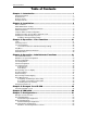
TABLE OF CONTENTS i Table of Contents Chapter 1: Introduction .................................................................. 1 Paragon II Overview...................................................................................................................1 Product Photos...........................................................................................................................2 Product Features........................................................................................
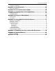
ii PARAGON II USER MANUAL Illegal Configuration .................................................................................................................62 Loop-Back Configuration..........................................................................................................62 Appendix A: Specifications .......................................................... 63 CAT5 Cable Guidelines.......................................................................................................
TABLE OF FIGURES iii Table of Figures Figure 1 Paragon II Base Units ........................................................................................................2 Figure 2 P2-UMT832, P2-UST, and P2CIM-PS2 .............................................................................2 Figure 3 Installation Diagram............................................................................................................6 Figure 4 Login Menu........................................................
iv PARAGON II USER MANUAL Figure 47 Stacking - Single Base Configuration with P2-UMT832M and P2-UMT832S................55 Figure 48 Stacking - Single Base Configuration with P2-UMT832M and P2-UMT832S................55 Figure 49 Stacking - Single Base Configuration with P2-UMT832M and P2-UMT832S................56 Figure 50 Stacking - Single Base Configuration with P2-UMT1664M and P2-UMT832S..............56 Figure 51 Stacking - Single Base Configuration with P2-UMT832M and P2-UMT1664S..............
CHAPTER 1: INTRODUCTION 1 Chapter 1: Introduction Congratulations on your purchase of Raritan’s Paragon II! The Paragon family is about breaking away from the traditional, expensive model of server management – one server, one dedicated monitor, one dedicated keyboard.
2 PARAGON II USER MANUAL Product Photos Figure 1 Paragon II Base Units Figure 2 P2-UMT832, P2-UST, and P2CIM-PS2
CHAPTER 1: INTRODUCTION 3 Product Features • • • • • • • • • • • • • • • • • • • • • • • • • • • 2U design supports 16 users, 64 servers (model P2-UMT1664M) 1U design supports 8 users, 32 servers (model P2-UMT832M) 1U design supports 4 users, 42 servers (model P2-UMT442) 1U design supports 2 users, 42 servers (model P2-UMT242) Expands to 32 users with Raritan’s UKVMP2 or CIMPAC8 Expands to 64 users with Raritan’s HUBPAC8 Locates users and servers up to 1,000 feet apart Supports high-resolution video – up
4 PARAGON II USER MANUAL Package Contents Each Paragon Base Unit (P2-UMT242, P2-UMT442, P2-UMT832M, or P2-UMT1664M) ships with: • • • • • • • • (1) Base Unit (2) 20-ft. (6.1-m) CAT5 test cables (1) Pair of rackmount brackets and associated screws (1) 6-ft. (1.
CHAPTER 2: INSTALLATION 5 Chapter 2: Installation Important! The Paragon and all devices you want to attach to it must be unplugged and powered OFF prior to installation. Basic Installation 1. 2. 3. 4. 5. 6. 7. 8. Connect power cord to the Main Switching Unit. Optional Stacking Support: − Connect power cord to a Stacking Unit. − Connect one end of a stacking cable to the "Expansion Port Out" on the back of the Stacking Unit.
6 PARAGON II USER MANUAL Optional 7 6 1 2 3 8 4 5 Figure 3 Installation Diagram
CHAPTER 2: INSTALLATION 7 Initial Administrative Testing To verify that an attached server can be viewed and controlled through the Paragon system: 1. When you first power ON the Paragon Base Unit, an attached User Station, and the User Station’s attached monitor; a Login Menu will be displayed on the monitor. Type admin (all lowercase) in the User Name field and press the [Enter] key. Type raritan (all lowercase) in the Password field and press the [Enter] key.
8 PARAGON II USER MANUAL A video-gain adjustment is available to focus the video image, which can be especially useful if you are using an LCD flat-panel monitor. To make this adjustment, activate the OSUI (if you have not done so already) by rapidly pressing the keyboard’s [Scroll Lock] key twice. Use the [+] and [-] (plus- and minussign) keys on the keyboard’s numeric keypad to adjust the video image until it appears to be in focus.
CHAPTER 2: INSTALLATION 2. 9 Line 2: User port status message: “A/N User (1, 2, 3 …) → None” User port status displays a scrolling status of all user ports, one user port per second. The User’s active channel, 1 through 256, is displayed after the user port number.
10 PARAGON II USER MANUAL 1. Display Ver./SN (Firmware Version and Serial Number): Displays current version of firmware and unit’s serial number. Firmware: 2C1 SN: CPB80347 Figure 11 Display Ver. and SN 2. Test User UST1 (User Station): Used by administrator to check if user stations (UST1s) are functioning properly. Press the [ ] or [ ] button to change user port number. Display will read “OK”, “None”, or “Failed. Press [ESC] to return to normal display.
CHAPTER 2: INSTALLATION 7. 11 Re-Configure: Paragon II will automatically configure the system as computers or devices are added or removed. However, the system administrator can use this function to scan and re-configure the system manually. When complete, it will return to normal display. Re-Configure Searching Now… Figure 16 Auto Configure 8. Set IP Address: As administrator, you may change Paragon II’s IP address directly from the front panel of the device.
12 PARAGON II USER MANUAL Initial Configuration Note: This section includes full instructions for how to install single Base Units, cascades of multiple base units, or stacking switches. Follow the simplified procedure previously outlined in Basic Installation to install a simple Paragon system with a single Base Unit. See Appendix B: User Station Direct Mode, to install a “direct mode” User Station-to-CIM system with no Base Units.
CHAPTER 2: INSTALLATION 13 Installing a Paragon System with a Single Base Unit If installing a single Paragon Base Unit, keep in mind the maximum numbers of user stations and server CPUs you can connect: • • • • 2 user stations and 42 CPUs to a P2-UMT242 4 user stations and 42 CPUs to a P2-UMT442 8 user stations and 32 CPUs to a P2-UMT832M 16 user stations and 64 CPUs to a P2-UMT1664M Important! All Paragon components, CPUs, and monitors must be turned OFF and unplugged before installation. 1. 2.
14 PARAGON II USER MANUAL 3. Initially configure the User Station. a. The Login Menu should be displayed on the User Station’s attached monitor. If the [Scroll Lock] LED on the User Station’s attached keyboard is blinking, the Paragon is ready to accept hotkey commands, which can be used with the OSUI to login, select servers, or administer the system. Figure 19 Login Menu for a P2-UMT832M If the monitor instead displays a “.....No connection to Paragon.....
CHAPTER 2: INSTALLATION 5. 6. 15 Connect a P2CIM-PS2 and its server CPU. a. Connect the cable strands of an appropriate P2CIM-PS2 to the desired ports on a server CPU: i. P2CIM-PS2 (IBM PS/2 compatible CPUs): Plug the HD15 strand into the CPU’s HD15 VGA video port. Plug the purple 6-pin mini-DIN keyboard strand into the CPU’s 6-pin mini-DIN keyboard port. Plug the light green 6-pin mini-DIN strand into the CPU’s 6-pin mini-DIN mouse port. ii.
16 PARAGON II USER MANUAL c. The Channel Configuration menu will appear. Use the up- and down-arrow keys to move the yellow highlight to the Name field for the channel port number where you installed the CPU and press the [Enter] key. The highlight should turn light blue. Figure 22 Channel Configuration Menu of a P2-UMT832M d. 7. Edit the name (it should turn green when you start typing). Press the [Enter] key when you finish, and then press [S] to save the new name. e.
CHAPTER 2: INSTALLATION 17 Installing a Cascaded Paragon System Paragon II’s channel port capacity can be expanded by installing a cascade of Base Units. In a “two-tiered” cascaded system, one or more subsidiary Base Units are connected to the channel ports of a master Base Unit. If you fully populate a second tier, you can add a third tier by connecting additional subsidiary Base Units to the channel ports of Base Units in the second tier.
18 PARAGON II USER MANUAL 6. Configure the channel ports in your system. (Check the [Scroll Lock] LED on one of your user-station keyboards. If it is blinking, the Paragon is ready to accept hotkey commands from that user station. Hotkey commands can be used with the OSUI to login, select servers, or administer the system.) a. At the Login Menu, type admin in the User Name field and press the [Enter] key. In the Password field, type the default password raritan (all lowercase) and press the [Enter] key.
CHAPTER 2: INSTALLATION d. 19 The Channel Configuration menu will appear. Use the up- and down-arrow keys and [PageUp] and [PageDown] keys to approach channel ports to which subsidiary Base Units are connected. These will be shown in white with their default device names in the Name column and their types in the Device column: “P242” for a 2 x 42 Base Unit (P2-UMT242), “P442” for a 4 x 42 Base Unit (P2-UMT442), “P832” for an 8 x 32 Base Unit (P2-UMT832M), or “P1664” for a 16 x 64 Base Unit (P2-UMT1664M).
20 PARAGON II USER MANUAL press the [Enter] key, then a channel port for a CPU attached to the second-tier Base Unit and press the [Enter] key. If you can properly access and operate the chosen CPU, the second-tier Base Unit is properly installed. m. Repeat steps c through l for all remaining (if any) second-tier Base Units attached to the master Base Unit. n.
CHAPTER 3: OPERATION – USER FUNCTIONS 21 Chapter 3: Operation – User Functions User functions for configuration and operation of your Paragon II system are processed through the OnScreen User Interface (OSUI). To activate the OSUI at any time, press the system’s hotkey (the factory default is [Scroll Lock]) twice in quick succession. Login Log on to access servers and other devices connected to the Paragon II system.
22 PARAGON II USER MANUAL 3. The Selection Menu will appear. To view other menus, use the function keys as described in the Help Menu section later in this chapter. Figure 28 Selection Menu for a P2-UMT832M Note: To Log out of the Paragon II system, press the function key [F9] while the OSUI is on-screen.
CHAPTER 3: OPERATION – USER FUNCTIONS 23 Selecting a Server Immediately following user login, the Selection Menu appears. Users who are already logged in can activate the Selection Menu by pressing the hotkey (the factory default is [Scroll Lock]) twice in quick succession, then pressing function key [F2]. The Selection Menu lists devices sorted either by channel port-ID number (“Ch. ID”) or alphabetically by the name of the server or other device on that channel port (“Name”).
24 PARAGON II USER MANUAL Figure 30 Selection Menu in order by Name The Selection Menu displays up to eight channel ports per page; total number of pages appears in the upper right-hand corner, for example “Page 2/5” indicates that you are on the second of five pages. Use the [PageUp] and [PageDown] keys on your keyboard to move between the pages. Once you have selected a CPU as described on the following pages, Paragon II will switch to that channel port.
CHAPTER 3: OPERATION – USER FUNCTIONS 25 Once you switch to a different channel port, you can continue switching by pressing the hotkey (factory default is [Scroll Lock]) twice rapidly to activate the Selection Menu. If you want to return to your previously selected channel port without seeing any OSUI menus, press the “previous channel port” command key (factory default is [Num Lock]) twice rapidly.
26 PARAGON II USER MANUAL User Customization When the OSUI is active, invoke the User Profile Menu by pressing function key [F4]. This menu displays Paragon II’s configuration and allows you to set preferred operating parameters for individual user accounts. Figure 31 User Profile Menu To view or change your user profile: 1. If the OSUI is not already active, activate it by pressing the hotkey (factory default is [Scroll Lock]) twice in quick succession. 2. Press [F4] to access the User Profile screen.
CHAPTER 3: OPERATION – USER FUNCTIONS 27 User Profile Parameters and How to Change Settings • • • • • • • • • Scan Mode: Indicates how Paragon II determines the length of time to pause at each channel port during autoscanning. Default setting is “Global” – the system pauses at each channel port for the same length of time (length of your choosing).
28 PARAGON II USER MANUAL You can change, delete, or reinstate your password (if “Allow Blank Password” is set to “Yes”) while the User Profile Menu is on-screen by pressing [P]. Type your old password at the first prompt. Type a new password up to eight characters long at the next prompt, and press the [Enter] key. To delete your password, press the [Enter] key without typing anything in the field.
CHAPTER 3: OPERATION – USER FUNCTIONS 29 Keyboard-Controlled OSUI Functions Use the following function keys to access the Paragon’s OSUI functions: PRESS… [F1] [F2] [F3] [F4] [F5] [F6] [F7] [F8] [F9] [Shift] + [F9] [F10] [F11] [F12] [Esc] WHEN YOU WANT TO… View the Help Menu Access the Selection Menu in order to view or select channel ports or view group IDs or scan rates Access Power Control Menu for associated Channel Access the User Profile Menu in order to view and change user-specific operating pa
30 PARAGON II USER MANUAL Information Menu When the OSUI is open, activate the Information Menu by pressing function key [F8]. This menu displays the “vital statistics” of the User Station that your user station is attached to, including its firmware and hardware revisions, its serial number, which console port (user port) on the Base Unit attached to it, and the number of KVM switches and PC CPUs that can be accessed through it.
CHAPTER 4: OPERATION – ADMINISTRATOR FUNCTIONS 31 Chapter 4: Operation – Administrator Functions The Administration Menu Administrators can use the Administration Menu to set security classes, maintain user names and privileges, and manage the system configuration, including controlling user access to Paragon II and all connected devices. Note: Administrative user IDs assigned to group 00 have complete access to all of the Administration Menu’s submenus.
32 PARAGON II USER MANUAL Guidelines for System Configuration • • • • Only one user should attempt to modify/update the System Administration Menu at one time (especially the User Configuration and Channel Configuration options). Z-CIMs should be added one at a time to a Z-CIM chain. The Administrator should read from message banner that the database has been completely updated before adding a new Z-CIM.
CHAPTER 4: OPERATION – ADMINISTRATOR FUNCTIONS • • • • • • 33 zeroes if necessary, type in a two-digit number of minutes from 01 to 99, or use the up- and downarrow keys to increment and decrement the current value by 1 respectively. The default setting is 05. If Logoff Timeout is set to “Off,” the number in this field will have no effect. Operation Mode: Any of the three ways in which the Paragon system handles requests from multiple users for access to the same channel port.
34 PARAGON II USER MANUAL User Configuration As administrator, use the User Configuration Menu to add, delete, and edit user names and security rights, and to display the current connection status for each user. Figure 36 The “left end” of the User Configuration Menu This menu displays one user’s information in each row. There are two “sides” of this menu, indicated by the right-pointing arrow at the top of the menu. The fields and columns on the “left side” of this menu: • • • • User: Your user name.
CHAPTER 4: OPERATION – ADMINISTRATOR FUNCTIONS 35 Press the [Tab] key or the right-arrow key to move to the “right end” of the menu and display users’ connection information: The Connection column displays which channel port (if any) each active user is currently connected to. Figure 37 The “right end” of the User Configuration Menu You can also perform three other functions at this menu: • • • Add a new user by pressing the [Insert] key.
36 PARAGON II USER MANUAL Channel Configuration As administrator, use the Channel Configuration Menu to edit or initialize a P2CIM-PS2. You can change the device name, individual scan rate, device type, and group IDs associated with each server or device. When you save Channel Configuration changes, Paragon II will update each affected P2CIM-PS2 as necessary. Figure 38 The “left end” of the Channel Configuration Menu This menu displays one channel port’s information in each row.
CHAPTER 4: OPERATION – ADMINISTRATOR FUNCTIONS 37 While the cursor is in the Device column, press [Tab] or the right-arrow key to move to the “right end” of this menu and display devices’ group information: The Group columns display which groups (if any) the device has been assigned to.
38 PARAGON II USER MANUAL User Station Profile As administrator, select Option 4 from the Administration Menu to activate the User Station Profile to set the global keyboard type and video delay. Keyboard Type The Paragon’s OSUI supports three types of keyboard mappings: Select either “English” – the default is U.S. English, “French,” or “German”.
CHAPTER 4: OPERATION – ADMINISTRATOR FUNCTIONS 39 Group Settings (Access Rights) To assign access rights to users and security levels to server CPUs in a Paragon system, assign users to user groups with defined rights and CPUs to channel port groups with defined accessibility. Each group can contain multiple users or CPUs. By default, all users start out assigned to user group 00 and all CPUs start out assigned to channel port group 00.
40 PARAGON II USER MANUAL THESE USER GROUPS... ...CAN ACCESS THESE CHANNEL PORT GROUPS: 00 through 99 (all CPUs) 00, 0x, and x0 through x9 00 0x (01 through 09) For example: 01 can access 00, 01, and 10 through 19; 02 can access 00, 02, and 20 through 29, etc. xy (10 through 99) 00, 0x, and xy For example: 10 can access 00, 01, and 10 23 can access 00, 02, and 23 97 can access 00, 09, and 97, etc. THESE CHANNEL PORT GROUPS... ...
CHAPTER 4: OPERATION – ADMINISTRATOR FUNCTIONS 41 Network Settings Configure the Paragon II’s network settings from the OSUI by pressing [F5] to activate the Administration Menu. Select option 5, Network Settings to adjust the network settings of the device. Figure 41 Network Settings Menu • • • • • • Current IP Address: This field allows administrators to configure the Paragon II’s address on the network. Use the arrow keys to scroll over to each byte and change the IP as needed.
42 PARAGON II USER MANUAL Autoscanning and Autoskipping As administrator, you can press [F6] to turn autoscanning on and off. When autoscanning is turned on, Paragon II switches sequentially and automatically from one channel port to the next, displaying each channel port’s video for the duration of the user’s global scan rate or the channel port’s individual scan rate (see Chapter 3: Operation – User Functions, User Customization), starting over at port 1 when it reaches the last channel port.
CHAPTER 4: OPERATION – ADMINISTRATOR FUNCTIONS 43 Power Management An administrator can control power to connected devices directly via the Paragon II OSUI. To use the power management features of Paragon II, you will need Raritan’s Remote Power Control Unit in one of three models, depending on your needs: − − − PCR8 – 8 port, 1U rack mount PCS12 – 12 port, “zero-U” vertical mount PCS20 – 20 port, “zero-U” vertical mount A special Raritan Power CIM (P2CIM-PWR) is available for use with this power strip.
44 PARAGON II USER MANUAL Controlling Power to an Outlet The addition of a power strip to the Paragon II system allows administrators to control the power to targets in two ways: Controlling power from the Server Selection Menu: Normal Paragon II operation involves browsing the list of devices in the OSUI and pressing [Enter] to switch to that target.
CHAPTER 5: PARAGON II AND Z-CIM 45 Chapter 5: Paragon II and Z-CIM If you have a local PC CPU that you want only the user(s) at a certain user station to be able to access, but you want that user station to be able to access the CPUs attached to the Paragon system as well, insert a P2CIM-PS2 dual-access CIM between a User Station and a Base Unit. To do this for a given user station: 1. If you have not already done so, install your Paragon system as described in Chapter 2: Installation. 2.
46 PARAGON II USER MANUAL Connecting Z-CIMs as Tiers The following diagram shows the final setup when connecting Z-Series Z4200U Z-CIMs as a tier: Cat 5e Cat 5e UKVMSPD UKVMSPD UKVMSPD Ca t5 e Cat 5e Cat 5e Z-CIM Terminator Last Z-CIM IN OUT PC Z-CIMs Z-CIMs Up to 42 Z-CIM Servers Up to 42 Back of P2-UMT832 Figure 42 Connecting a Z-CIM as a Tier to Paragon II Important: Z-Series installation requires that each computer be assigned a channel name as it is added to the Z-CIM chain.
CHAPTER 5: PARAGON II AND Z-CIM c. d. e. 47 Place the Z-CIM Terminator in the Z-CIM’s UTP IN port. Power ON computer. Optional: Connect a local user console to the UKVMSC Z-CIM. Perform Channel Configuration: 1. At a User Station Login Menu, type admin in the User Name field and press [Enter]. 2. Type “raritan” (all lowercase) in the Password field and press [Enter]. 3. Press [F5] to go the Administration Menu and select the Channel Configuration submenu. 4.
48 PARAGON II USER MANUAL Attach Z-CIM to Computer to be Added: For UKVMSPD Z-CIM: 1. Connect the 6-pin mini-DIN keyboard and mouse and HD15 video connectors on the UKVMSPD ZCIM to computer’s keyboard, mouse, and video ports. For UKVMSC Z-CIM with local port: 1. Connect CCPnn cable’s 6-pin mini-DIN and HD15 connectors to computer’s keyboard, mouse, and video ports. 2. Connect DB25 male end of CCPnn cable to DB25 female port on back of Z-CIM (UKVMSC). Attach new Z-CIM to the existing Z-CIM chain: 1.
CHAPTER 6: IBM X330 49 Chapter 6: IBM x330 Paragon II unit firmware versions 1P0 (UMT2161), 2C2 (UMT242, UMT442, and UMT8), or 3A2 (UMT1664) and User Station (UST1) firmware 4L2 or higher supports an IBM x330 chain of computers as a second tier by utilizing IBM’s Cable Chaining Technology (C2T) and Raritan Computer Interface Modules (CIMs), UKVMP-x330 or UKVMC-x330. An IBM x330 rack of up to 42 servers can be accommodated for each Paragon II Matrix Switch channel port.
50 PARAGON II USER MANUAL Install an IBM x330 Rack of Servers as a Tier to Paragon II: 1. Set up Paragon II following Basic Installation instructions, but reserve one channel port for each rack of IBM x330 servers to be connected. 2. Connect a Category 5e UTP cable to the reserved channel port on the back of the Paragon II unit. 3. Connect the other end of the category 5e UTP cable to the RJ45 port on a Raritan CIM UKVMP-x330 or UKVMC-x330. 4. Attach the CIM to IBM Break Out Cable from the x330 rack.
CHAPTER 7: CONFIGURATIONS 51 Chapter 7: Configurations When implementing complex tiered and stacked architectures for a Paragon system, there are important guidelines describing the legal and illegal configurations among devices in a Paragon system, and the procedures to make the system function in the appropriate manner that you must follow and procedures to make the system function in an appropriate manner.
52 PARAGON II USER MANUAL Tiered Configurations Standard Tiering Configurations Single Base Configuration Definition of Single Base configuration: • • • • Only UMT matrix switches can serve as base units. The base unit must always be the latest released version, both in hardware and firmware. A maximum of three (3) tiers, including the base unit, is permitted.
CHAPTER 7: CONFIGURATIONS 53 Multiple Base Configuration Definition of Multiple Base configuration: • • • • • Two or more UMT Matrix Switches serve as base units. The base unit must always be the latest released version, both in hardware and firmware. A maximum of three (3) tiers, including the base unit, is permitted. Upper-tier devices connect to two or more base UMTs.
54 PARAGON II USER MANUAL Stacked Configurations Definition of stacking configuration: • • • • • The P2-UMT Stacking Switch, a new switch device required for stacking configurations, expands the number of available channel ports in a single switch. It does not add user ports. − UMT Stacking Switch P2-UMT1664S has four 68-pin expansion ports. Two are input ports and two are output ports. The P2-UMT832S has only one 68-pin expansion input port and one output port.
CHAPTER 7: CONFIGURATIONS 55 Standard Stacking Configurations Single Base with Stacking Example A: Non-blocked System – P2-UMT1664M Standard configuration – any user can access any channel port in the system. I/P P2-UMT1664M P2-UST O/P P2-UMT1664S P2-UST Figure 46 Stacking - Single Base Configuration with P2-UMT1664M and P2-UMT1664S Example B: Non-blocked System – P2-UMT832M Standard configuration – any user can access any channel port in the system.
56 PARAGON II USER MANUAL Example D: P2-UMT832M Stacked and Tiered Standard configuration – any user can access any channel port in the system.
CHAPTER 7: CONFIGURATIONS 57 Example G: Illegal Configuration P2-UMT1664M I/P O/P I/P P2-UST P2-UMT832S 1A O/P P2-UMT832S 1B P2-UST Figure 52 Stacking - Single Base Configuration with P2-UMT1664M and P2-UMT832S Example H: Illegal Configuration I/P O/P P2-UMT832M P2-UST P2-UMT1664S P2-UST Figure 53 Stacking - Single Base Configuration with P2-UMT832M and P2-UMT1664S
58 PARAGON II USER MANUAL Non-Standard Tier Configuration Guidelines for Existing Firmware Versions • Non-Standard tier configurations are those configurations supported by Paragon II, but require special procedures in order to function properly.
CHAPTER 7: CONFIGURATIONS 59 Triangle Configuration The following procedure must be followed to ensure this configuration functions properly: − − After re-connection, all UMT Matrix Switches must undergo a FUNC reset to clear the switch database. This procedure should be performed starting from the third tier device down to the base unit. Execute the FUNC reset in the following order: UMT-3A → UMT-2A → UMT-Base 1.
60 PARAGON II USER MANUAL Diamond Configuration The following procedure must be followed to ensure this configuration functions properly: − − After re-connection, all UMT Matrix Switches should undergo a FUNC reset to clear the switch database. This procedure should be performed starting from the third tier device down to the base unit. Execute the FUNC reset in the following order: UMT-3A → UMT-2A → UMT-2B → UMTBase 1.
CHAPTER 7: CONFIGURATIONS 61 Redundant Configuration The procedure outlined below must be followed to ensure this configuration functions properly: − − − − − After installation, all UMT Matrix Switches should undergo a FUNC reset to clear the switch database. This procedure should be performed starting from the third tier device down to the base unit. Execute the FUNC reset in the following order: UMT-3A → UMT-3B → UMT-2A → UMT-2B → UMT-Base 1 → UMT-Base 2.
62 PARAGON II USER MANUAL In order to make a redundant configuration system operate more efficient, the following connection scheme between tiers is recommended: − − − − Assume there are two UMT Base devices, the UMT-Base1 and UMT-Base2 Assume there are three UMT second tier devices, the UMT-2A, UMT-2B, and UMT-2C Channel connection of UMT-Base1 Channel ports 3*N+1 (1, 4, 7….) connect to UMT-2A user ports sequentially, starting from user port 1 Channel ports 3*N+2 (2, 5, 8….
APPENDIX A: SPECIFICATIONS 63 Appendix A: Specifications PARAGON II UNIT P2-UMT1664M P2-UMT832M P2-UMT442 P2-UMT242 PARAGON II STACKING UNITS P2-UMT1664S P2-UMT832S PARAGON II USER STATIONS P2-UST PARAGON CIMS P2CIM-PS2 P2CIM-SUN P2CIM-USB P2CIM-SUSB P2CIM-PWR DESCRIPTION DIMENSIONS 16 users x 64 server ports, expansion slot, stacking port, network port 11.41” (W) x 17.32” (D) x 1.75” (H) 290mm (W) x 440mm (D) x 44mm (H) 12.52 lbs 100V/240V 5.68 kg 50/60 Hz 0.
64 PARAGON II USER MANUAL CAT5 Cable Guidelines Use only straight-through-pinned four-pair (eight-wire) Category 5 unshielded twisted pair (UTP) cables, terminated with standard RJ-45 plugs, for the CAT5 cabling links in your Paragon system. If your existing CAT5 site-wiring system meets these requirements, feel free to send the signals through your site’s patch panels, existing wiring, etc., but you should keep the number of patches and splices to a minimum to avoid degrading the video signals.
APPENDIX B: USER STATION DIRECT MODE 65 Appendix B: User Station Direct Mode A Paragon User Station set to Direct Mode can be directly connected to a Paragon CIM, either temporarily for emergency “crash cart” access or permanently for non-switched extension purposes, without having to go through a Base Unit. To make this kind of “Direct Mode” connection, take these steps: 1.
66 PARAGON II USER MANUAL
APPENDIX C: CONFIGURATION AND COMPATIBILITY 67 Appendix C: Configuration and Compatibility Configuration Matrix Paragon II UMT1664 /832 /442 /242 UMT1664S/832S Upper UMTx HW3 w/3.2 FW Tiers UMTx HW3 w/Current FW Base/Lower Tiers UMTx HW3 UMTx HW3 w/3.
68 PARAGON II USER MANUAL
APPENDIX D: PARAGON II RACK MOUNT 69 Appendix D: Paragon II Rack Mount Paragon II User Stations and most Base Units can be mounted in 1U (1.75", 4.4 cm) of vertical space in a standard 19" equipment rack; P2-UMT1664M Base Units can be mounted in 2U (3.5", 8.9 cm) of space. To rackmount a Base Unit, use the brackets and screws that came with the unit; to rackmount a User Station, use the RMKSMU rackmount kit.
70 PARAGON II USER MANUAL Rear Mount 1. 2. 3. 4. 5. Secure the cable-support bar to the front end of the side brackets, near the side brackets’ “ears,” using two of the included screws. Slide the User Station or Base Unit between the side brackets, with its rear panel facing the cablesupport bar, until its front panel is flush with the back edges of the side brackets. Secure the User Station or Base Unit to the side brackets using the remaining included screws (three on each side).
APPENDIX E: USING AUATC FOR RS-232 ACCESS 71 Appendix E: Using AUATC for RS-232 Access Introduction to the AUATC To use your Paragon II system to access a CPU or other device through an RS-232 port, attach one of our RS-232 serial CIMs (product code AUATC) to the device’s serial port as described in the first section of this Appendix. The AUATC is designed to emulate an ASCII terminal, converting keyboard input to RS232 data input and converting RS-232 data output for display on a VGA monitor.
72 PARAGON II USER MANUAL Operating the AUATC Screen Layout The AUATC produces eight-color video at 800 x 600 resolution, which can accommodate 32 lines of 80 text characters each. A typical ASCII terminal uses 24 lines, so the AUATC uses the eight extra lines to provide system-status and help information. These eight lines are divided so that four are at the top of the screen and four are at the bottom.
APPENDIX E: USING AUATC FOR RS-232 ACCESS 73 On-Line Mode When you operate the AUATC in On-Line Mode, the main screen area displays your interactions with the ASCII device, as if it were the screen of an ASCII terminal. Simultaneously, the data stream being output by the device is stored in an eight-page circular buffer, so you can not only access and operate the device, but you can also review its historical data as needed.
74 PARAGON II USER MANUAL Buffer Edit Mode The AUATC stores the most recent eight pages of data from the attached ASCII device in a circular buffer. After you switch the AUATC from On-Line Mode to Buffer Edit Mode by pressing [Alt] + [F4], you can review the contents of the buffer by moving the cursor with the arrow keys, [PageUp], [PageDown], [Home], and [End]. You can also edit the data in the buffer with [Insert], [Delete], [Backspace], and the other keys listed in the Help screen.
APPENDIX E: USING AUATC FOR RS-232 ACCESS 75 Configuring the AUATC Press [Alt] + [F2] to activate the Setup Screen, where you can select your desired serial-communication parameters (baud rate, etc.) and type of local video output. The initial parameters will always start at their factory defaults, so make sure that the serial port or device to which the AUATC is attached is temporarily configured for 9600 bps, 8 data bits, no parity, and 1 stop bit.
76 PARAGON II USER MANUAL To program any of your keyboard’s twelve function keys with commands or data items you frequently have to send the device, activate the Set Up Programmable Keys screen by pressing [Alt] + [F3]. Once a string (with a maximum length of sixteen characters) has been assigned to a key, pressing that key while in OnLine Mode will send the entire string to the device.
APPENDIX E: USING AUATC FOR RS-232 ACCESS 77 Troubleshooting the AUATC If you do not get a device prompt: 1. If the AUATC’s screen is displayed on your monitor with the top and bottom help windows, make sure that it indicates On Line status. If not, press [Esc] to return to On-Line Mode. 2. Make sure that the AUATC and the attached device are both receiving power. The AUATC’s power supply should be securely connected to both the AUATC and a working outlet.
78 PARAGON II USER MANUAL
APPENDIX F: EMULATING SUN KEYS WITH A PS/2 KEYBOARD 79 Appendix F: Emulating Sun Keys with a PS/2 Keyboard We recommend that you use a Sun keyboard and mouse at your user stations if there are any Sun CPUs in your Paragon system. If you must use a PS/2 keyboard to control a Sun CPU attached to your Paragon system, the Paragon is able to perform some keyboard emulation.
80 PARAGON II USER MANUAL
APPENDIX G: TROUBLESHOOTING 81 Appendix G: Troubleshooting SYMPTOM: No Power. All computers have no video display. Monitor video display for some connected computers is distorted. Keyboard non-functional, even though there is no keyboard error at power up. Cannot input to any computer. Repeated “Keyboard ERROR” at computer power-up. Keyboard suddenly locksup when a particular computer is selected, but works normally when other computers are selected.
82 PARAGON II USER MANUAL Multi-Tier Installation In a multi-tier configuration, the order of powering ON is critical to proper function. • • • • Last tier switches must be powered ON before the intermediate level of tier Intermediate tier switches must be powered ON before the base Paragon II unit can be powered ON. User Stations (UST1s) can be powered ON and OFF at any time as needed. There is a five-second ON/OFF down time in the UST1 or Paragon II power cycle.
APPENDIX H: FAQ 83 Appendix H: FAQ SUBJECT: What’s Different between Paragon and Paragon II QUESTION: What is the primary difference between Paragon and Paragon II? Backward Compatibility Will Paragon II work with my current Paragon installation? Stacking Paragon II is a stackable switch. Does this mean that I can stack logical units to increase the number of ports available? I would like to eliminate all the cables between cascaded Paragon units.
84 PARAGON II USER MANUAL SUBJECT: QUESTION: Can I restore my saved Paragon Overview files on Paragon II? Does each unit have a network port for firmware upgrades or just the base? Integrated Power Management What is “Integrated Power Management”? So I can access and control all my connected Power Units via the Paragon II OSD? Connecting Serial Devices I have a serially controlled device (i.e. Unix server, hub).
APPENDIX H: FAQ SUBJECT: Cabling 85 QUESTION: What UTP cable does Raritan recommend for use with Paragon II? Can I use standard Ethernet (10BASE-T) cable? Hot-key Functions Hot-key Functions - I don't want to use the "scroll lock" to activate hot-key. What are my options? Hot-plugging We have some mission critical servers and there are occasions when we may wish to disconnect a server from the Raritan switch and "hot-plug" a physical keyboard and mouse to operate the server.
86 255-30-6000 PARAGON II USER MANUAL