STRAIGHTENER OPERATING INSTRUCTIONS MODELS SBX SERIES (ADJUSTABLE PLATEN STOCK STRAIGHTENER – INCLUDES SA3 THROUGH SCX) (6-01) RAPID-AIR CORPORATION 4601 KISHWAUKEE ST. • ROCKFORD, IL 61109-2925 Phone: (815) 397-2578 • Fax: (815) 398-3887 • Web Site: www.rapidair.
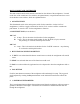
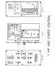
INDEX 1. Straightener Layout Sheet Pg. 3 2. Platen Adjustment Bulletin Pg. 4 3. Installation Pg. 5 4. Start-Up Procedure Pg. 5 5. Electrical Controls Layout Pg. 8 6. Dancer Arm Adjustment Explanation Pg. 10 7. Standard and Optional Components Pg. 11 8. Operations Pg. 12 9. Maintenance Pg. 13 10. Trouble Shooting Guide Pg. 14 11. Taut Stock Explanation Pg. 16 12. Electrical Schematics Pg. 26 13. Mechanical Parts List Pg. 29 14. Typical Stamping Layout Pg.
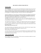
SBX SERIES POWERED STRAIGHTNER INSTALLATION The straightener that you just received is fully assembled and tested and ready to be put into position. CAUTION: Due to shipment vibration, the straightener should be checked to be sure that all screws and bolts are secure and all electrical components are in place inside the cabinet. Visually inspect the complete machine for physical damage due to shipment and handling. If the straightener was damaged in shipment, contact the carrier first and then Rapid Air.
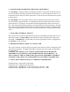
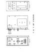
MAIN CONSOLE AND CONTROLLER The main control console with controls is mounted on the cabinet of the straightener. Located on the face of the console are five switches, one potentiometer, one push-button and one or two circuit breaker reset switches, which are explained below. 1. ON/OFF SWITCH This illuminated switch is the main power switch for the controller. On the 120 VAC straighteners, it will be a toggle switch and on the 230 VAC version it will be a mushroom push-button.
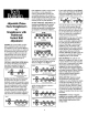
6. DANCER ARM LOOP HEIGHT AND RANGE ADJUSTMENT A. Loop Range—The loop range switch adjusts the amount of travel that the dancer arm will move to provide the full range of speed on the straightener. It has three positions with a “0” as the least travel from slowest to fastest speed and a “2” has the most movement between slowest to fastest speed. B. Loop Height—The loop height switch is used for setting the start position of the control arm.
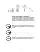
DANCER ARM LOOP HEIGHT ADJUSTMENT Three different loop sensing arm operating positions are selected manually during set-up. By selecting the higher number, the zero point of the dancer arm is raised from it’s rest position to the angle shown (as indicated 0-2). The dancer arm will move from rest position to the angle selected before the pallet reel begins to rotate.
STANDARD STRAIGHTENER COMPONENTS CURVE UP/DOWN ADJUSTMENT Some applications have dies that cannot accept anything but flat stock and other dies run better with the material curving up or down to miss the built in edge required in the die. Before this feature was added, operators would under straighten or over straighten the material to suit their needs but in doing so would severely change the material entering the die. This not only caused feeding problems but part quality problems.
OPERATION Once the straightener has been tested and all the functions work then it should be tested for what it was designed to do and that is to remove coil set. Retract all of the idler rolls and the exit pinch roll to a position so when the cover is closed the material is not being deformed. Open the cover of the straightener and position the edge guides for maximum width.
MAINTENANCE LUBRICATION Gear transmission: The reservoir oil capacity is about 4 OZ. The reservoir oil should be changed every 2000 hours and should be filled the oil level site gauge. Use MOBILE 600W cylinder oil or equivalent. This is a non synthetic oil. Rolls: Although the rolls should be cleaned periodically they never have to be greased as all the rolls have permanently lubricated bearings. Drive Belt: At the oil change interval, check for belt tension and wear.
TROUBLESHOOTING GUIDE MAIN SWITCH ON BUT NOT LIT 1. CB tripped a. Reset CB 2. Unit not plugged into main power. a. Plug into main power source 3. No power in incoming line. a. Check outlet. b. Check power cord. 4. Loose wiring a. Check terminals and connections MOTOR CREEPS IN STOP POSITION 1. R1 & R3 pot on 69100034 board not correctly adjusted. a. Readjust pots so tables stops. Call factory. UNIT TURNS BUT WON’T JOG 1. Selector switch not in jog position. a. Select jog. 2.
3. If running with external control a. Check that the external/loop arm switch is in the external position. 4. Height switch setting too high. a. Set height setting to “0”. 5. Percent speed pot set too low. a. Adjust percent speed pot to 100%. 6. Fuses blown. a. Check fuses & circuit breaker. 7. No AC voltage at DC drive board. a. Check wiring 8. Check signal voltage between P2 to I2 on DC drive. 0-6 VDC—Ramm 0-9 VDC—Regen Drive while moving dancer arm a.
69100034 TAUT STOCK OUTPUT The 69100034—Proportional control board has a taut stock output. The output must be wired to a solid state relay as the max current draw is 20 MA. The solid state relay’s contact can then be incorporated into the electrical control circuitry. The output can be wired so that the relay is either on or off with the dancer arm down. When the dancer arm reaches the set point for taut stock, the relay switches state.
RAPID-AIR CORPORATION RAMM SOLID STATE DC MOTOR SPEED CONTROL SAFETY WARNING—PLEASE READ CAREFULLY This product should be installed and serviced by a qualified technician, electrician or electrical maintenance personnel familiar with its operations and the hazards involved.
PLUG IN HORSEPOWER RESISTOR A Plug-In Horsepower Resistor must be installed to match the RAMM to the motor horsepower and voltage. See table 2 for the correct value. Plug-In Horsepower Resistors are stocked by your distributor. TABLE 2. PLUG IN HORSEPOWER RESISTOR CHART* MOTOR HORSEPOWER RANGE** Armature Armature Voltage Voltage 90-130 VDC 180 VDC Plug-in Horsepower Resistor Resistance Value (ohms) 1/4 1/2 3/4 1*** .05 .025 .015 .
INTRODUCTION The RAMM Full Wave Solid State DC Motor Speed Control represents the latest state of the art design achievable through modern technology. Features include: Integrated Circuitry Used to control and amplify command and reference levels with both closed and open loop feedback to provide superior motor regulation. (Speed changes due to load, line voltage, or temperature variations are held to minimum levels.) High Quality Components Selected and tested for proven dependability.
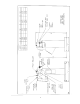
Fig. 1. Basic RAMM Connection Diagram CAUTION: Do not bundle potentiometer connections (P1, P2, P3) and inhibit Connections (I1, I2) with AC line or motor wires. B. VOLTAGE FOLLOWING. All models can be controlled with an isolated analog reference voltage (0-6VDC) in lieu of the main speed potentiometer. The voltage is connected to P2 (+) and F-. The control output voltage will linearly follow the input voltage. The source impedance of the input should be 10k ohms or less.
(Use Buss ABC, Littlefuse 326 ceramic fuse or equivalent.) 2. Armature Fuse can be chosen in accordance with the fuse chart. Note: The armature fuse is calculated based on the approximate full load DC current rating of the motor times a form factor of 1.5. If motor has characteristics not consistent with these approximations, a different fuse value may have to be used. Fuses are available from your distributor. TABLE 4. ARMATURE FUSE CHART 90VDC MOTOR 180VDC MOTOR APPROX.
NOTE: In order for the IR comp and CL trimpot settings to be correct, the proper Plug-in Horsepower Resistor must be installed for the particular motor and input volt age being used. Do no attempt to change the settings of the trimpots unless absolutely necessary since they are factory adjusted to near optimum settings. The following procedure, presented in order of adjustment sequence, should be used when readjusting all trimpot functions. Fig 2. ACCEL/DECEL TRIMPOT ADJUSTMENT A. Acceleration Start.
To set the CL to factory specification adjust as follows: 1. Set speed control knob at approximately 30-50% CW rotation. Set CL trimpot to full CCW position. 2. Connect a DC ammeter in series with the armature lead. 3. Lock shaft of motor (be sure CL pot is in full CCW position). Apply power and rotate CL pot CW slowly until DC ammeter reads 1.5 times motor rating (do no exceed 2 times motor rating, Max. CW position.) NOTE: If only an AC ammeter is available, it can be installed in series with the AC line.
LIMITED WARRANTY—RAMM 125, 225, 225D For a period of one (1) year from date of original purchase Rapid-Air Corporation will repair or replace without charge devices which our examination proves to be defective in material or workmanship. This warranty is valid if the unit has not been tampered with by unauthorized persons, misused, abused or improperly installed and has been used in accordance with the instructions and/or ratings supplied.