RAPID LIGHT LOOP OPERATING INSTRUCTIONS MODELS RLL RAPID-AIR CORPORATION 4601 KISHWAUKEE ST. • ROCKFORD, IL 61109-2925 Phone: (815) 397-2578 • Fax: (815) 398-3887 • Web Site: www.rapidair.
OPERATING INSTRUCTIONS RLL (RAPID LIGHT LOOP) Part number 10900462 and 10900463 INSTALLATION: The RLL unit, when received, should be checked for shipping damage. If damage has occurred, contact the carrier that handled the shipment first and then Rapid-Air to report the damage. The RLL unit is shipped pretested, set to a working height of 30”, and set for payout operation.
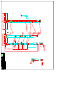
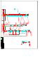
The interface board contains a Payout/Rewind switch and user adjustable Max. output and Jog speed potentiometers. Refer to the adjustments section prior to changing these setpoints. The RLL is factory set for (Payout) mode and will send a 6 VDC output to the controlled unit when the material is at the top of the loop. All loop control functions are fixed and never need adjustment. See the adjustment section prior to selecting the Rewind mode. There is one user replaceable fuse.
CAUTION: Keep clear of rotating hardware during thread up. Turn power off of take up reel during thread up or place take up reel in the JOG mode. Make certain material is taut and above RLL upper beam prior to power up. Set the Payout/Rewind switch to Rewind on the Control Pwb of the RLL. This will automatically switch light beam operation to give full speed at the bottom of the loop and the motor to be full off if the top light beam is interrupted by material.
MAX. VOLTAGE OUTPUT. R33 This pot is set for normal 6 VDC operation. Adjust this pot to increase voltage to 10 VDC only if required by controlled device drive. PAYOUT/REWIND MODE SELECT Select either payout or rewind mode from this switch. Payout mode is selected by setting the toggle switch towards the interior of the board. TROUBLESHOOTING ELECTRONIC CIRCUITRY 69100089 RECEIVER BOARD 1. Place in payout mode. Block bottom light beam. Controlled device motor should stop if on.