PALLET MASTER (PMD) OPERATING INSTRUCTIONS MODELS (INCLUDES PMD35 & PMD50. 115VAC, 1PH, 60HZ) RAPID-AIR CORPORATION 4601 KISHWAUKEE ST. • ROCKFORD, IL 61109-2925 Phone: (815) 397-2578 • Fax: (815) 398-3887 • Web Site: www.rapidair.
Rapid Air Corporation OPERATING INSTRUCTIONS PMD 35 &50 INSTALLATION The machine that you have just received was disassembled for shipping purposes. Please check all parts for shipping damage. If damage has occurred, contact the carrier first and then Rapid Air to report the damage. Upon opening the shipping crate, you will find the main base table control arm, drum, and a counter weight.
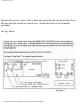
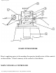
Rapid Air Corporation Remove the access cover of the control arm and route the electrical wires from the base into the electrical control area. Attach the wires to the terminals provided. See fig. below. file:///C|/Web_develop/Pallet%20Master.
Rapid Air Corporation CONTROL ARM SETUP & INSTALLATION Determine the direction of rotation in which the material shall decoil as it leaves the pallet reel. Position the pallet reel in line with the entrance side of the press. Install the control arm assembly in the control head hub such that the counter weight is pointing toward the turntable. Position the control head and arm and check that it is locked before proceeding The following sketches will show some basic arrangements of the pallet reel.
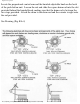
Rapid Air Corporation Locate the proportional control arm and the knurled adjustable knob on the back of the push button unit. Loosen the nut and slide the square drum rod into the slot provided behind the knurled knob, making sure that the drum rod is between the two stops provided. Attach the drum to the drum rod and the counter weight onto the rod provided. See Drawing (Fig. RA-4) file:///C|/Web_develop/Pallet%20Master.
Rapid Air Corporation DANCER ARM LOOP HEIGHT ADJUSTMENT Eight different loop sensing arm operating positions are selected manually during set-up. By incrementing the thumbwheel height switch, the zero point of the dancer arm is raised from its rest position to the angle shown (as indicated 0-7). The dancer arm will move from rest position to the angle selected before the pallet reel begins to rotate.
Rapid Air Corporation 10 degree— Loop sensing arm travels through a 10 degree arc to vary turntable rotation speed from slow to full speed as controlled by % speed pot. 5 degree— Only the first 5 degrees of loop sensing arm travel is required to control turntable rotation from slow through full speed as controlled by % speed pot. file:///C|/Web_develop/Pallet%20Master.
Rapid Air Corporation START UP PROCEDURE Prior to applying power to the machine the operator should review all the controls on the machine. A brief summary of the controls is listed below. MAIN CONSOLE & CONTROLLER file:///C|/Web_develop/Pallet%20Master.
Rapid Air Corporation The main control console & controls are mounted on the end of the raised extended arm of the machine. It was installed to keep the operator clear of the coil plate. Located on the face of the console are seven switches and one potentiometer, which are explained below. 1. DIRECTIONAL CONTROL - The direction control switch selects the direction the pallet reel will rotate, clockwise or counterclockwise. 2.
Rapid Air Corporation set up. Speed is adjusted on the 69100053 terminal board on the electrical control sub-panel. 7. DANCER ARM LOOP HEIGHT & RANGE ADJUSTMENT a. Loop Range - The loop range thumbwheel adjusts the amount of travel the dancer arm will move to provide the full range of speed of the pallet reel. b. Loop Height - This thumbwheel is used for setting the start position of the control arm. The setting determines when the reel will start turning.
Rapid Air Corporation TAUT STOCK The TAUT STOCK feature monitors the loop between the PMD and the external equipment. If the loop gets small enough to possibly cause damage to the PMD, the interface contacts change state and stops the PMD. If it is desired to monitor the PMD, then the following write up will explain how to connect and adjust this feature. The TAUT STOCK feature is built into the Rapid-Air board #69100035 and wired to external terminals 7-8-9.
Rapid Air Corporation file:///C|/Web_develop/Pallet%20Master.
Rapid Air Corporation Start the reel and raise the dancer arm so that the reel is running maximum speed. Raise the dancer arm up to a point that the stock would be taut. Hold the dancer arm at this position and adjust the pot R9 of board 69100034 until the contact changes state. Release the dancer arm. The contact should return to normal state. Raise and lower the dancer arm 2 to 3 times to ensure that the contact functions properly. Disconnect the OHM meter and connect the customer interface.
Rapid Air Corporation The system is designed to operate on 120HZ 50/60 power. The unit is provided with a power cord that is connected to a terminal strip located under the pallet reel coil plate. The power is then distributed to the proper control panel. The distributed power is circuit breaker protected and is intended as a power source for the pallet reel and any additional Rapid Air accessory. Plug the main power cord to any grounded 120 VAC, 20 amp receptacle.
Rapid Air Corporation 1. Switch “ON” 2. RUN/STOP/JOG - “RUN” 3. Slowly push (rotate) the control arm toward the turntable to start the rotation. A. If the table turns in the wrong direction, turn power switch “OFF” and reverse the rotation direction switch. Then turn switch “ON”. B. The turntable speed should increase as the control arm is moved toward the table. OPERATION 1. Place the coiled stock on the turn table. Center the material on the turn table so the coils are concentric with the table. 2.
Rapid Air Corporation This should be done after the material has been started through the die so final alignment has been achieved. 6. Adjust the height on the control arm. Adjust the spring pressure on type “B” or adjust counter balance weight on type “A” control arm to just offset the effect of the material loop so the control arm will go back to the starting (rest) position when the press is not demanding material. After this has been completed, turn TRUN/STOP/JOG to “RUN”. You are now ready to run. 7.
Rapid Air Corporation A. Used to contain the ID of the coil from springing inward and falling down into the coil below. B. Also used to keep coil in place when the diameter becomes very small, otherwise the coil may slide off the unit at the smallest diameter. C. The overall length of the ID keeper can be cut off to suit. Depending on the majority of coil ID ranges used. OPTIONAL EQUIPMENT The remote jog consists of approx.
Rapid Air Corporation Motor—The DC drive motor commutator brushes should be checked after every 1500 hours of use. When the brushes are worn down to 5/8” or less, they should be replaced with new brushes. 2. TROUBLE SHOOTING GUIDE MAIN SWITCH ON BUT NOT LIT 1. CB tripped a. Reset CB 2. Unit not plugged into main power. a. Plug into main power source. 3. No power in incoming line. a. Check outlet. b. Check power cord. 4. Loose wiring a. Check terminals and connections.
Rapid Air Corporation 1. R1 & R3 pot on 69100034 board not correctly adjusted. a. Readjust pots so table stops. Call factory. UNIT TURNS BUT WON’T JOG 1. Selector switch not in jog position. a. Select jog. 2. Jog pot on 69100053 board not adjusted correctly. a. Adjust pot. Call factory. 3. Maximum speed pot on Ramm board set too low. a. Adjust pot. UNIT ON BUT MOTOR WON’T RUN. (ARMATURE VOLTAGE PRESENT ON RAMM BOARD) 1. Check TB-4 of 69100035 board. Terminal 1&2. a.
Rapid Air Corporation a. Worn brushes or motor defective. Call factory. NOTE: Refer to drawing RA-2 for location of components, sequence check form Ramm board to motor. UNIT ON BUT MOTOR WON’T RUN. (NO ARMATURE VOLTAGE ON RAMM BOARD) 1. Selector switch not in run position. a. Turn selector switch to run position. 2. Transition plug not installed. a. If not using E control, install transition plug supplied with unit. 3. Thumbwheel height setting too high. a. Set height setting to “0”. 4.
Rapid Air Corporation 6. No AC voltage at DC drive board. a. Check wiring. 7. Check Signal voltage between P2 to I2 on DC drive while moving dancer arm. 0-6 VDC—Ramm 0-9 VDC—Regen Drive a. If there is a signal, check continuity between I1 & I2. If continuity, replace 69100035 board or call factory. If no continuity, replace D.C. drive or call factory. 8. Check line voltage input of 69100034 board, 120 VAC, TB-1 a. Check wiring. Call factory. 9. Check pico fuse 69100034 board (f1). a.
Rapid Air Corporation connections between panduit connector #TC3 of 69100034 board and panduit connector #TC3 of 69100035 board and panduit connector #PT3 of 69100053 board. This should be a continuity check for tight connections. Call factory for assistance. b. If voltage is not present move on to step 12. 12. Check voltage between pin #2 of TB-2 & pin #5 of TB-7 on 69100053 board while moving the dancer arm from minimum to maximum position. a. If voltage varies 2.
Rapid Air Corporation If using 220 vac 1 phase input. Wire as indicated by drawing fig. RA-2. This unit cannot be used with 120 vac 1 phase input unless the Ramm Board is changed to a 120 volt controller. See fig. RA-2. RAPID-AIR CORPORATION RAMM SOLID STATE DC MOTOR SPEED CONTROL SAFETY WARNING—PLEASE READ CAREFULLY This product should be installed and serviced by a qualified technician, electrician or electrical maintenance personnel familiar with its operation and the hazards involved.
Rapid Air Corporation electric motors, switches, coils solenoids and/or relays. Eye protection must be worn when working with control under power. This product is constructed of materials (plastics, metals, carbon, silicon, etc.) which may be a potential hazard. Individual material safety data sheets (MSDS) are available upon request.
Rapid Air Corporation 5. Nominal trimpot settings are as follows (expressed in % of full CW rotation): TABLE 1: NOMINAL TRIMPOT SETTINGS MIN (minimum speed): 15% CL (current limit/torque): 65% MAX (maximum speed): 65% ACCEL (acceleration start): 20% IR (IR compensation): 25% DECEL (deceleration stop): 20% PLUG IN HORSEPOWER RESISTOR A Plug-In Horsepower Resistor must be installed to match the RAMM to the motor horsepower and voltage. See table 2 for the correct value.
Rapid Air Corporation TABLE 2. PLUG IN HORSEPOWER RESISTOR CHART* file:///C|/Web_develop/Pallet%20Master.
Rapid Air Corporation * Motor horsepower and armature voltage must be specified when ordering so that proper resistor will be supplied. ** For overlapping motor horsepower range use lower value Plug-In Horsepower Resistor. *** Auxiliary heatsink must be used to achieve HP rating. INTRODUCTION The RAMM Full Wave Solid State DC Motor Speed Control represents the latest state of the art design achievable through modern technology.
Rapid Air Corporation Transient Protection Used to prevent failure of the power bridge circuit caused by voltage spikes on the AC line. High Reliability When used in accordance with instructions in this manual, the RAMM will provide years of trouble free operation. A. Initial Setup and Wiring i. General Instructions 1. Install proper size Plug-In Horsepower Resistor. (see table 2) 2.
Rapid Air Corporation TABLE 3. MINIMUM SUPPLY WIRE SIZE REQUIREMENTS file:///C|/Web_develop/Pallet%20Master.
Rapid Air Corporation B. VOLTAGE FOLLOWING. All models can be controlled with an isolated analog reference voltage (0-6VDC) in lieu of the main speed potentiometer. The voltage is connected to P2 (+) and F-. The control output voltage will linearly follow the input voltage. The source impedance of the input should be 10K ohms or less. The Min trimpot can be used to provide an offset speed. If an offset is not required adjust the Min to 0+ or 0– speed as desired.
Rapid Air Corporation C. FUSING. The RAMM has provision for a built in AC line fuse and armature fuse. The AC line fuse protects the control against catastrophic failure– if the fuse blows, the control is miswired, the motor is shorted or grounded, or the RAMM control is defective. The armature fuse provides overload protection for the motor and control. Choose the proper size armature fuse by multiplying the maximum DC motor amps by 1.7.
Rapid Air Corporation (Use Buss ABC, Littlefuse 326 ceramic fuse or equivalent.) 2. Armature Fuse can be chosen in accordance with the fuse chart. Note: The armature fuse is calculated based on the approximate full load DC current rating of the motor times a from factor of 1.5. If motor has characteristics not consistent with these approximations, a different fuse value may have to be used. Fuses are available from your distributor. file:///C|/Web_develop/Pallet%20Master.
Rapid Air Corporation ADJUSTMENTS AND CONTROL FUNCTIONS Warning: If adjustments are made under power, insulated adjustment tools file:///C|/Web_develop/Pallet%20Master.
Rapid Air Corporation must be used and eye protection must be worn. The RAMM has been factory adjusted to provide 0-full speed using the speed control knob. Minimum and Maximum speed trimpots are provided to change the speed from other than 0-full speed. The Acceleration (ACCEL) trimpot is provided to allow for a smooth start over an adjustable time period each time the AC power is applied or the speed pot is rotated.
Rapid Air Corporation Fig 2. ACCEL/DECEL TRIMPOT ADJUSTMENT file:///C|/Web_develop/Pallet%20Master.
Rapid Air Corporation A. Acceleration Start. The ACCEL is factory set at approximately .2 seconds. To readjust to different times, set the knob to the desired position as indicated in Fig 2. B. Deceleration. The DECEL is factory set to provide a ramp-down time of .2 seconds. To change the ramp-down time, adjust the DECEL trimpot as indicated in Fig 2. C. Minimum Speed Adjustment.
Rapid Air Corporation E. Current Limit (CL/Torque Adjustment). CL circuitry is provided to protect the motor and control against overloads. The CL also limits the inrush current to safe level during startup. The CL is factory set to approximately 1.5 times the full load rating of the motor. (CL trimpot is nominally set to approximately 65% of full CW rotation).
Rapid Air Corporation To set the CL to factory specifications adjust as follows: 1. Set speed control knob at approximately 30-50% CW rotation. Set CL trimpot to full CCW position. 2. Connect a DC ammeter in series with the armature lead. 3. Lock shaft of motor (be sure CL pot is in full CCW position). Apply power and rotate CL pot CW slowly until DC ammeter reads 1.5 times motor rating (do not exceed 2 times motor rating, Max. CW position.) F. IR Compensation Adjustment.
Rapid Air Corporation The RAMM is now compensated to provide minimal speed change under large variations of applied load. NOTE: If only an AC ammeter is available, it can be installed in series with the AC line. Follow above instructions; however, set AC amperage at .75 times motor rating. NOTES: 1. Excessive IR comp. will cause control to become unstable, which causes motor cogging. 2. For tach feedback applications the IR comp can be set to minimum rotation (full CCW).
Rapid Air Corporation examination proves to be defective in material or workmanship. This warranty is valid if the unit has not been tampered with by unauthorized persons, misused, abused or improperly installed and has been used in accordance with the instructions and/or ratings supplied.
Rapid Air Corporation file:///C|/Web_develop/Pallet%20Master.
Rapid Air Corporation file:///C|/Web_develop/Pallet%20Master.