multi-stroke control OPERATING INSTRUCTIONS Rapid-air corporation 4601 Kishwaukee St. • Rockford, IL 61109-2925 Phone: (815) 397-2578 • Fax: (815) 398-3887 • Web Site: www.rapidair.
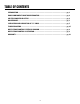
table of contents INTRODUCTION........................................................................................................................................... pg. 3 BOARD COMPONENTS AND TROUBLESHOOTING............................................................................... pg. 4 AIR FEED PROGRESSION SET-UP............................................................................................................. pg. 4 MAINTENANCE........................................................
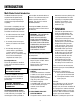
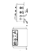
introduction Multi-Stroke Control Introduction The Multi-Stroke Control, when coupled with a Rapid-Air feed, increases the feed length by up to 9 times the original feed length capability. path to allow an external device to operate. The solid state relay will remain until the reset switch is tripped. The contact is rated at 0.5 AMPS/120 VAC. The control is completely self-contained and requires only 3 interface points, which are provided on the outside of the electrical enclosure.
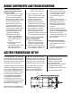
b0ard components and troubleshooting There are two switches on the board for changing the operation of the cut-to-length. 1. The first switch is a bat or toggle switch. It is located just above the transformer on the board. When the switch position is to the left of the board, then the air feed will run at a normal speed.
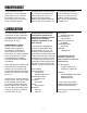
maintenance The air feed needs very little maintenance. The most important part to watch is the air. Too much oil or water in the air can cause the air feed to start running erratic. Screws should be checked periodically to be sure they are tight. This includes the switch mounting brackets, if present, as they can loosen up over time due to the vibration and high impact movement of the air feed. A visual check of the air feed every morning before running it will help assure many hours of running time.
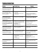
troubleshooting Problem Possible Cause Remedy Feed and stock clamps work, but slide block does not move when actuating valve is depressed. – Pilot operated valve is stuck. – Check for grit, swollen nylon or swollen “O” rings. Excessive leakage of air from exhaust hole beneath speed adjusting screw when actuating valve is in up position. – Poppet not seating on bottom of valve hole.
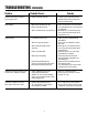
troubleshooting (continued) Problem Probable Causes Remedy Feed has difficulty pushing last part of progression. – Feed is not inline with die. – A slight angular adjustment of the feed will reduce the binding of the stock on the die guides. Over feeding. – Stock excessively dirty or oily. – Feed is operating too fast. – Clean unit and stock. Run and retest. – Turn speed adjusting screw clockwise to slow down.
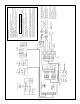
NOTE-2: THE MULTI-STROKE UNIT CYCLE IS CONTROLLED BY THE PRESS CYCLE. TURNING OFF THE MULTI-STROKE UNIT BEFORE THE PRESS CYCLE IS COMPLETE COULD ALLOW THE PRESS TO CONTINUE CYCLING. NOTE-1: IF THE RESET SWITCH IS ALLOWED TO BE HELD OPEN THEN AN UNCONTROLLED START CYCLE COULD BE INITIATED. NORMALLY CLOSED LIMIT SWITCH (SUPPLIED BY CUSTOMER) TO BE MOMENTARILY OPENED AFTER WORK CYCLE OF THE EXTERNAL EQUIPMENT TO PROVIDE A RESET SIGNAL. ISOLATED NORMALLY OPEN CONTACT PROVIDED TO CUSTOMER.
warranty Warranty Terms & Conditions All sales by the company are made subject to the following terms and conditions. please read. warranty - The Company warrants, for a period of one year from date of shipment by the Company, that the product shipped is free from defects in material and workmanship. this warranty is exclusive and in lieu of all implied warranties in law, including merchant - ability. The Company obligation under this warranty is limited to repairing or replacing, F. O. B.