dual swivel reel with display keypad operating instructions Models 100 & 1000 series Rapid-air corporation 4601 Kishwaukee St. • Rockford, IL 61109-2925 Phone: (815) 397-2578 • Fax: (815) 398-3887 • Web Site: www.rapidair.
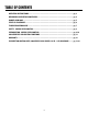
table of contents operating INSTRUCTIONS..................................................................................................................... pg. 3 MECHANICAL OPERATING PROCEDURES.............................................................................................. pg. 4 DANCER ARM LOOP.................................................................................................................................... pg. 5 START-UP PROCEDURE............................................
operating instructions Installation 1. The machine that you have just received is fully assembled and ready to be put into position. Due to shipment vibration the machine should be checked to be sure all screws and bolts are tight. Visually inspect the machine for damaged parts due to shipment. If the machine is damaged in shipment, contact the carrier first to report the damage, and then Rapid-Air. 2. Install the machine on a level surface with sufficient clearance for loading and unloading coils. 3.
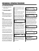
mechanical operating procedure To Load Or Unload A Coil Ring A) If your reel has a fixed center shaft go to Step 1. B) If your reel has an adjustable center shaft go to Step 2. Step 1: Release and remove the outer coil retainer from the shaft. Load or unload the coil ring. Replace and secure the outer coil retainer. The reel is now ready for production. Step 2: Release and remove the outer coil retainer from the shaft. If unloading, adjust the centering arms to a position that they have released the coil.
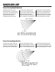
dancer arm loop Dancer Arm Loop Height Adjustment Eight different loop sensing arm operating positions can be selected during set-up. The material thickness determines the dancer arm rest position. Once the material is threaded up and the dancer arm is resting on the material and the reel runs in the rest position then select a higher number on the height adjustment until the reel stops rotating.
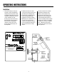
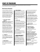
Start up procedure Prior to applying power to the machine the operator should review all the controls on the machine. A brief summary of the controls is listed below. Main Console & Controller The main pushbutton control box is mounted on the top of the reel frame. Located on the face of the console are eleven pushbuttons, one display, one on/off switch, one circuit breaker, one external loop plug and inside the box is motor board and one potentiometer when required, all of which are explained below. 1.
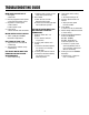
troubleshooting guide MAIN SWITCH ON BUT NOT LIT 1. CB tripped a. Reset CB 2. Unit not plugged into main power. a. Plug into main power source. 3. No power in incoming line. a. Check outlet. b. Check power cord. 4. Loose wiring a. Check terminals and connections. MOTOR CREEPS IN STOP POSITION 1. “Min” speed pot on RAMM board out of adjustment. UNIT TURNS BUT WON’T JOG 1. Jog function was not selected a. Select jog. 2. Jog speed has not been set up a. Call factory. UNIT ON BUT MOTOR WON’T RUN.
safety warning – please read carefully RAMM Solid State DC Motor Speed Control This product should be installed and serviced by a qualified technician, electrician or electrical maintenance personnel familiar with its operation and the hazards involved.
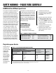
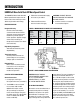
INTRODUCTION RAMM Full Wave Solid State DC Motor Speed Control The RAMM Full Wave Solid State DC Motor Speed Control represents the latest state-of-the-art design achievable through modern technology. 3. Follow the recommended supply wire sizes as per table 3. 4. Follow the NEC and other electrical codes that apply. CAUTION: SEPARATE BRANCH PROTECTION MUST BE PROVIDED ON 240V CIRCUITS. 5. Connect control in accordance to connection diagram.
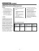
INTRODUCTION (continued) RAMM Full Wave Solid State DC Motor Speed Control CAUTION: 1. The voltage feeding P2 and F– must be isolated from the AC line. Do not ground P2 or F– to set up a zero ground reference. 2. Do not bundle signal wires to P2 and F– with AC line motor connections. If signal wires are over 18”, use shielded cables. C. FUSING The RAMM has provision for a built in AC line fuse and armature fuse.
adjustments and control functions RAMM Adjustments And Control Functions WARNING: If adjustments are made under power, insulated adjustment tools must be used and eye protection must be worn. The RAMM has been factory adjusted to provide 0-full speed using the speed control knob. Minimum and Maximum speed trimpots are provided to change the speed from other than 0- full speed.
warranty Limited Warranty – RAMM 125, 225, 225D For a period of one (1) year from date of original purchase Rapid-Air Corporation will repair or replace without charge devices which our examination proves to be defective in material or workmanship. This warranty is valid if the unit has not been tampered with by unauthorized persons, misused, abused or improperly installed and has been used in accordance with the instructions and/or ratings supplied.
13 Pushbutton Control Reel 1000 Series Dual Swivel – 1/2-1 HP
14 Pushbutton Control Reel 1000 Series Dual Swivel – 1-1/2 HP
15 Pushbutton Control Reel 1000 Series Dual Swivel – 2 HP
16 Pushbutton Control Reel 1000 Series Dual Swivel – 3 HP