DUAL SWIVEL REEL OPERATING INSTRUCTIONS MODELS 100 & 1000 SERIES RAPID-AIR CORPORATION 4601 KISHWAUKEE ST. • ROCKFORD, IL 61109-2925 Phone: (815) 397-2578 • Fax: (815) 398-3887 • Web Site: www.rapidair.
OPERATING INSTRUCTIONS DUAL SWIVEL REELS Installation 1. The machine that you have just received is fully assembled and ready to be put into position. Due to shipment vibration the machine should be checked to be sure all screws and bolts are tight. Visually inspect the machine for damaged parts due to shipment. If the machine is damaged in shipment, contact the carrier first to report the damage, and then Rapid Air. 2.
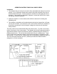
MECHANICAL OPERATING PROCEDURE To Load or Unload a Coil Ring a) If your reel has fixed center shaft go to step 1. b) If your reel has an adjustable center shaft go to step 2. Step 1 Release and remove the outer coil retainer from the shaft. Load or unload the coil ring. Replace and secure the outer coil retainer. The reel is now ready for production. Step 2 Release and remove the outer coil retainer from the shaft. If unloading, adjust the centering arms to a position so that they will release the coil.
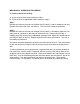
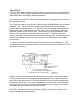
DANCER ARM LOOP HEIGHT ADJUSTMENT Eight different loop sensing arm operating positions are selected manually during setup. By incrementing the thumbwheel height switch, the zero point of the dancer arm is raised from it’s rest position to the angle shown (as indicated 0-7). The dancer arm will move from rest position to the angle selected before the pallet reel begins to rotate.
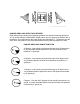
START UP PROCEDURE Prior to applying power to the machine the operator should review all the controls on the machine. A brief summary of the controls is listed below. MAIN CONSOLE & CONTROLLER The main control console & controls are mounted on the end of the raised extended arm of the machine. It was installed to keep the operator clear of moving parts such as the reels. Located on the face of the console are four switches and one potentiometer which are explained below. 1.
TAUT STOCK The Taut Stock feature monitors the loop between the reel and the external equipment. If the loop gets small enough to possibly cause damage to the reel, the interface contacts change state and stop the external equipment. If it is desired to monitor the reel then the following write up will explain how to connect and adjust this feature. The Taut Stock feature is built into the Rapid-Air board 69100035 and wires to external terminals 7-8-9.
TROUBLE SHOOTING GUIDE MAIN SWITCH ON BUT NOT LIT 1. CB Tripped a. Reset CB 2. Unit not plugged into main power a. Plug into main power source 3. No power in incoming line. a. Check outlet. b. Check power cord. 4. Loose wiring a. Check terminals and connections. MOTOR CREEPS IN STOP POSITION 1. R1 & R3 pot on 69100034 board not correctly adjusted. a. Readjust pots so table stops. Call factory. UNIT TURNS BUT WON’T JOG 1. Selector switch not in jog position. a. Select jog 2.
4. Percent speed pot set too low. a. Adjust percent speed pot to 100% 5. Fuses blown. a. Check fuses on D.C. drive board. 6. No AC voltage at DC drive board. a. Check wiring. 7. Check signal voltage between P2 and I2 on DC drive, while moving dancer arm. 0-6 VDC - Ramm 0-9 VDC - Regen Drive a. If there is a signal, check continuity between I1 & I2. If continuity, replace 69100035 board or call factory. If no continuity, replace D.C. drive or call factory. 8.
RAMM SOLID STATE DC MOTOR SPEED CONTROL SAFETY WARNING - PLEASE READ CAREFULLY This product should be installed and serviced by a qualified technician, electrician or electrical maintenance personnel familiar with its operations and the hazards involved.
PLUG IN HORSEPOWER RESISTOR A Plug-in horsepower resistor must be installed to match the RAMM to the motor horsepower and voltage. See table 2 for the correct value. Plug-in horsepower resistors are stocked by your distributor. TABLE 2 - PLUG IN HORSEPOWER RESISTOR CHART Motor Horsepower Range ** Armature Voltage 90-130 VDC 1/4 1/2 3/4 1** Armature Voltage 180 VDC 1/2 1 1-1/2 2*** Plug in Horsepower Resistor Resistance Value (ohms) Rapid-Air P/N .05 .025 .015 .
INTRODUCTION The RAMM full wave solid state DC motor speed control represents the latest state of the art design achievable through modern technology. Features Include: Integrated Circuitry Used to control and amplify command reference levels with both closed and open loop feedback to provide superior motor regulation. (Speed changes due to load, line voltage or temperature variations are held to minimum levels).
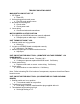
Fig. 1 Basic RAMM Connection Diagram CAUTION: Do not bundle potentiometer connections (P1, P2, P3) and inhibit connections (I1, I2) with AC line or motor wires. B. VOLTAGE FOLLOWING. All models can be controlled with an isolated analog reference voltage (0-6VDC) in lieu of the main speed potentiometer. The voltage is connected to P2 (+) and F-. The control output voltage will linearly follow the input voltage. The source impedance of the input should be 10K ohms or less.
1. AC line fuse is chosen according to the maximum rating of the control: 12 AMP fuse for all motors up to 3/4 HP-90V and 1 1/2 HP-180VDC. 25 AMP fuse for all motors 1 and 1/2 HP-90V and 2 and 3 HP-180VDC. (Use Buss ABC, Littlefuse 326 ceramic fuse or equivalent.) 2. Armature Fuse can be chosen in accordance with the furs chart. Note: The armature fuse is calculated based on the approximate full load DC current rating for the motor times a form factor of 1.5.
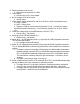
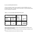
The following procedure, presented in order of adjustment sequence, should be used when readjusting all trimpot functions. Fig. 2 ACCEL/DECEL TRIMPOT ADJUSTMENT A. Acceleration Start. The ACCEL is factory set at approximately .2 seconds. To readjust to different times, set the knob to the desired position as indicated in fig. 2. B. Deceleration. The DECEL is factory set to provide a ramp down time of .2 seconds. To change the ramp-down time, adjust the DECEL trimpot as indicated in fig. 2. C.
3. Lock shaft of motor (be sure CL pot is in full CCW position). Apply power and rotate CL pot CW slowly until DC ammeter reads 1.5 times motor rating (do not exceed 2 times motor rating, max. CW position). NOTE: If only an AC ammeter is available, it can be installed in series with the AC line. Follow above instruction; however, set AC amperage at .75 times motor rating. F. IR Compensation Adjustment. IR compensation is provided to substantially improve load regulation.
LIMITED WARRANTY - RAMM 125, 225, 225D For a period of one (1) year from date of original purchase Rapid-Air Corporation will repair or replace without charge devices which our examination proves to be defective in material or workmanship. This warranty is valid if the unit has not been tampered with by unauthorized persons, misused, abused or improperly installed and has been used in accordance with the instructions and/or ratings supplied.